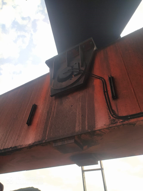
The Port of Dover has installed an advanced monitoring system with integrated Meteor MRC cameras to gather data on ferry berthing events and the real-world performance of berth fender systems. The project aims to gather data that can be used to better inform maintenance planning and alert the port’s asset engineers to any significant berthing events that might compromise the effectiveness of the berthing fenders.
Sensors have been installed to measure the magnitude of fender displacement when ferries are berthing, with the MRC camera providing a visual verification of each vessel. By combining these datasets, fender displacement measurements can be correlated with individual berthing events.
“The Meteor camera provides us with ‘eyes on-site” explains Nick Slater from I&M Solutions, who has been delivering the monitoring contract with Justin Roffey of Geo-Sub Ltd. “As soon as a sensor registers an approaching vessel, the data logging system is activated, which in turn triggers the camera, allowing methodical collection of berthing data. This improves the response time for the port’s engineers, saves time and money, and provides valuable operational context to support informed maintenance, asset integrity and future fender management decisions.”
Ensuring safe operations in a busy port
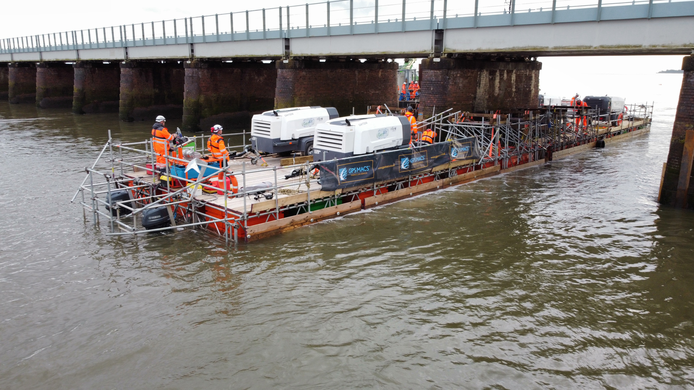
The Port of Dover is the UK’s busiest international ferry port, handling over 11 million passengers and 33% of the UK’s trade in goods with the EU. It is therefore necessary for ferry arrivals (approximately 2 per hour) to access the port in a safe, sustainable and timely manner. To support this, each of the port’s 6 car ferry berths are fitted with a range of different fender designs in order to absorb low velocity forces when a ferry berths. This makes the berthing process smoother for passengers, whilst also reducing the potential for damage to either the quay wall or the vessel.
Periodically, the fenders require routine service and maintenance to ensure long-term optimal performance. These interventions are typically time-based, and for a pre-specified number of compressions. Traditionally, maintenance schedules are therefore heavily informed by fender manufacturers’ published specifications.
With the monitoring system in place the operational and maintenance teams at Dover are now able to use quantitative measurements, to inform maintenance scheduling and planning for repairs. This helps to extend the life of the fenders and reduce the likelihood of any reactive interventions that may require a berth to be closed, temporarily reducing port capacity.
Port of Dover fender monitoring system
One of the primary considerations when designing a monitoring system for a UK port, is the robustness of the equipment. Storms, waves, salt spray and high winds combine to present a particularly challenging location for precise measurements.
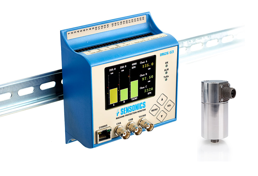
Geo-Sub / I&M Solutions installed a long-range Vega radar sensor to detect ferry arrivals at the berth. A further 5 sensors were installed at selected fenders, measuring the distance from the quay wall to the rear of the fender, with all data captured by bespoke wireless loggers. Once a vessel is detected, the 5 fender sensors are activated, instructing the loggers to record measurements at 5Hz while the vessel berths.
A specialist remote camera from Meteor Communications monitors the sensors and records images for each ferry docking. Meteor’s MCE mini pillar camera with IR illuminator was installed towards the end of 2024, and Nick Slater says: “It has performed flawlessly for the past year, delivering high-quality images in all weathers to corroborate sensor data, and enable us to view site conditions without requiring engineers to attend the berth unnecessarily.” Reflecting on the choice of remote camera, Nick adds: “I have installed hundreds of MRC cameras over the past 10 years and have no doubts about their reliability and performance.”
The Meteor camera communicates via secure mobile network links with image visualisation provided by the MeteorCloud® platform - a secure web portal for viewing camera images, diagnostics and historic imagery.
Summary
The deployment of the fender monitoring system has delivered a number of important benefits:
- Measures cyclical compression of fender components, and identifies any reduction of fender performance
- Supports condition-based maintenance scheduling, rather than relying solely on fixed time-based intervals:
- Lowers costs
- Improves berth uptime
- Lowers operational carbon footprint
- Improves both ferry and port safety
- Provides ‘eyes on site’ and helps engineers assess conditions remotely where appropriate.
- Informs future fender design.
Looking forward, Gennaro Acquaviva, Senior Engineer at the Port of Dover says: “The combined camera and fender monitoring system has given us valuable insight into the real-world performance of our berth infrastructure. By combining fender displacement data with visual records of berthing operations, we can better understand the forces being imposed on the fenders and how the system responds over time.
“The key benefit for us is the ability to make more informed engineering decisions. This data supports condition-based maintenance, improves our understanding of fender integrity, and helps us plan replacements or design improvements based on evidence rather than assumption. This has important benefits for safety, operational reliability and cost control, while also supporting sustainability by helping us avoid unnecessary replacement of serviceable components and reducing the carbon impact associated with premature asset renewal.”
Meteor’s products provide real-time access to vitally important field data, with two main themes. Remote water quality monitoring stations measure background levels, enabling trend analysis and the identification of pollution from diffuse and point sources. Remote, low-power, rugged cameras provide visualisation of key assets such as construction sites, flood gates, weirs, flumes, screens, grills etc. Both the cameras and the water quality monitoring stations provide immediate access to current conditions with alarm capability, which enables prompt remedial action, as well as the optimisation of maintenance activities.
Meteor Communications provides a wide range of off-the-shelf and bespoke monitoring solutions. Most can be deployed within minutes, are solar powered and do not require significant infrastructure to run. Cloud-based data is accessed via secure login to the Meteor Communications data centre. This is achieved using any web-enabled device and provides instant access to live and stored data, which includes an interactive graphical display.
Meteor Communications has a large installed base of remote monitoring stations and the company’s turnover has increased rapidly. In 2026 Meteor Communications was included in the Sunday Times 100 Tech - Britain’s fastest-growing private technology companies.