New and Improved Electronic Flow Control for Smarter Compressed Air Use

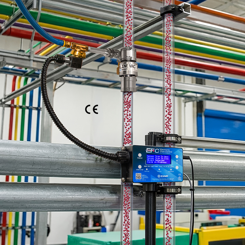
EXAIR's newly redesigned EFC™ Electronic Flow Control makes it easier than ever to minimize compressed air use in automated industrial processes. The EFC pairs a photoelectric sensor with programmable timing control to automatically turn on compressed air only when needed, eliminating waste during production gaps. The latest design introduces asynchronous timing for greater control over operating cycles, convenient external programming that eliminates the need to remove the enclosure cover to make adjustments, and a sleek new appearance built for today's industrial environments.

The EFC's asynchronous timing lets users independently control ON and OFF intervals, providing greater flexibility in matching compressed air delivery to application demands. A compact photoelectric sensor detects objects up to 3 feet (1 meter) away, while the EFC automatically controls the compressed air supply through a fast-acting solenoid valve. Ideal for blowoff, drying, cooling, conveying, and static elimination applications, EFC models control compressed air flows up to 350 SCFM. The new design also allows operators to quickly adjust programming from outside the enclosure, making setup and changes easier.

 The EFC is part of EXAIR's complete line of compressed air optimization products designed to help manufacturers identify, measure, and eliminate unnecessary compressed air consumption. Other optimization products include Digital Flowmeters for monitoring air usage, Ultrasonic Leak Detectors for leak detection, and Digital Sound Level Meters for evaluating workplace noise. Combined with EXAIR's engineered compressed air products and experienced Application Engineers, these tools provide manufacturers with practical ways to reduce compressed air demand, improve process efficiency, and lower operating costs. https://www.exair.co/efc1

Teledyne FLIR's Industry-First UL 2684 Listing Strengthens the Case for Thermal Image Fire Detection in Europe

The milestone gives European fire engineers and risk professionals independent evidence when specifying thermal image fire detection, complementing established European and national approval requirements.

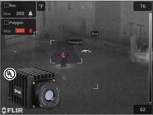
Teledyne FLIR's A40 and A70 (Axx-Series) thermal imaging cameras are the first models to achieve UL 2684 listing. They are listed as thermal image fire detectors under ANSI/CAN/UL 2684, the Standard for Video and Thermal Image Detectors for Fire Alarm Systems. Although UL 2684 is a North American standard, the Teledyne FLIR milestone has important implications for Europe.

European fire detection is supported by a mature standards and certification environment covering established technologies such as smoke, point heat, aspirating, and flame detection. Radiometric thermal image detection has no harmonised European product standard of its own, and is addressed through project-specific approval pathways and national certification schemes, including VdS in Germany and CNPP in France. These pathways support the assessment of systems that continuously measure temperature across a scene and identify abnormal heat before smoke or flame develops.

EN 54-10 covers flame detection, including the flame-response capability of certified thermal cameras. UL 2684 is written specifically for video and thermal image detectors, evaluating and testing them as fire detection devices.

In the United States, the 2025 edition of NFPA 72, the National Fire Alarm and Signaling Code, created a dedicated category for thermal image fire detection (Sec. 17.12), which requires thermal image fire detection systems to be listed for the purpose of fire detection.

UL 2684 is a North American product standard that provides an independent benchmark for the performance of video and thermal image fire detectors. In Europe, it can support the technical evidence presented through the applicable European approval pathway. European regulatory requirements, CE marking obligations, relevant EN 54 standards, national certification schemes such as VdS and CNPP continue to apply, and the approving authority determines project acceptance.

“Fire engineers work from evidence, and the strongest evidence is a published benchmark with an accredited laboratory behind it,” said Matthew Hasty, Global Vertical Director for Science, Automation, and Early Fire Detection at Teledyne FLIR. “That is what the listing adds for Europe. It gives the people building the technical case something independent to build on.”

What the listing changes is the strength of the evidence behind the specification. A consultant, a risk engineer, or a fire protection professional can now put forward a detector whose fire performance has been tested against a published benchmark by an accredited laboratory and show the reviewer where that benchmark came from. That benchmark is concrete: flaming wood, flammable liquid, and polyurethane fires with defined response criteria, plus the environmental, electrical, and durability programme around them. In a submission that has to be argued rather than ticked off against a standard, that is a considerably stronger position than manufacturer test data.

The listing tests fire performance. The everyday value sits in the instrumentation. A radiometric thermal camera is a calibrated measuring instrument, not a camera that renders heat in colour. Every pixel in the scene reports a temperature, many times a second. Teledyne FLIR Early Fire Detection solutions monitor defined regions of interest and report minimum, average, and maximum values for each, with alarms set on absolute thresholds, on the difference between regions, and on rate of rise. The system responds to how heat is behaving rather than only to how hot something is, and it leaves a record: a measured value, a location in the scene, a history behind it. That record is what an approving authority or an underwriter can actually review.

Demand is coming from operators. Waste and recycling sites deal with deep-seated fires in stored material. Manufacturers run bearings, motors, and hydraulic lines that heat up well before they ignite. Battery energy storage installations face thermal runaway. Data centres concentrate electrical load, and a failing connection runs hot long before it smokes. Rooftop solar arrays develop hotspots at connectors and modules, often on roofs with no conventional detector at all. In each case, thermal imaging provides continuous temperature-based monitoring that can identify developing heat conditions before smoke, flame, or conventional heat thresholds are reached.

Thermal imaging is line-of-sight, so a camera protects what is in its field of view. In practice that means specific high-value assets: a switchboard, a battery enclosure, a conveyor run. It works alongside conventional detection rather than in place of it. The cameras are also multispectral: detection is thermal, while an integrated visible camera supplies the picture, so an alarm arrives with video of what caused it. An operator can see what they are dealing with before stopping a line, and a stoppage that turns out to have been unnecessary is money the site never gets back.

For projects being designed in Europe today, the UL 2684 listing provides independent evidence that can strengthen the specification and approval case. It works alongside the applicable European, national, and project-specific approval pathway.

For more information about Axx-Series thermal imaging cameras and Teledyne FLIR's early fire detection solutions, visit flir.com/fire-life-safety.
 

New, no waste RFID label printer

brady_oct_1.jpeg

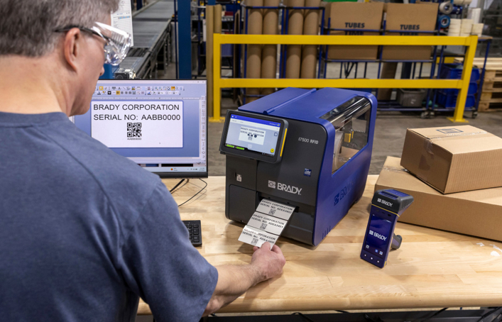
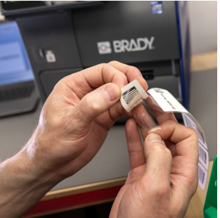
Print and encode the first RFID label right, with 0 label waste. Brady Corporation’s new i7500 RFID label printer does not waste a single label in calibration.

Unique technology

The new BradyPrinter i7500 Industrial RFID Label Printer prints and encodes the first RFID label right. Tested competitive models waste 10 to 30 labels after each consumable change.

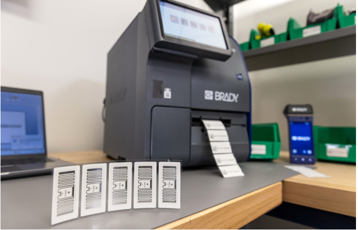
The printer also automatically locates label RFID chips to select the right internal antenna and power level that optimally encode UHF RFID labels currently loaded in the printer. In most RFID printers this input needs to be provided manually. The Brady printer’s unique technology reduces label waste even further, limits void labels, avoids time loss in production environments and adds great practicality for non-expert RFID printer users. Brady claims the technology accurately recognises RFID chips, even on labels as small as 15 mm width.

The patent-pending print and encoding technologies included in Brady’s new i7500 RFID make the printer extremely easy to use in a wide range of industrial contexts. They enable industries to easily switch UHF RFID label types on a single printer, without suffering label waste with each consumable change.

Fast, automated setup

With setup time for large, small, on-metal (up to 2mm thick) and off-metal UHF RFID labels under 3 minutes, the i7500 RFID is 25 to 2 times faster than most competitive models.

The printer’s exceptional material setup and calibration speed strengthens its ability to protect industrial operational throughput. Designed to keep the line moving, Brady’s new RFID printer reduces support interventions, UHF RFID tag scrap, component scrap, unplanned downtime and production bottlenecks, all at a print & encode speed of 3 seconds per label.

Brady_oct_2.jpeg

High accuracy data

From large pallet labels to small component tags, the i7500 RFID printer includes automated UHF RFID label encoding verification. At the same time it can add human legibles and tiny machine-readable QR-codes and barcodes for legacy applications, in both 300 and 600 dpi.

Data can be sourced from company systems and sent to the printer via Ethernet, USB, Wi-Fi and Bluetooth. Common data standards can all be printed and encoded, including GS1 for worldwide unique RFID EPC codes and barcodes on item-level.

Next level track & trace

The BradyPrinter i7500 RFID brings on-premise RFID printing to a wider range of industries. Highly reliable and easy to use, the printer does not require extensive technical expertise nor large amounts of excess labels to waste in calibration.

The new i7500 RFID label printer is part of Brady’s complete industrial RFID solution that also includes reliable RFID labels, RFID readers and RFID software. Together, these solution components enable next level track & trace advantages.

Brady_oct_3.jpeg

Trigger IoT- events and automations when scanning a label or a specific volume of labels. Enable home-in applications on tagged assets. Improve just-in-time tracking, automated inventory and cargo control. Strengthen compliance in advanced industrial supply chains. Or link products to their digital passports with RFID. The BradyPrinter i7500 RFID can give any asset, item and product a unique digital identity that can be read from a distance, without needing line of sight. The new RFID printer completes Brady’s quality traceability offer that enables reliable track and trace in any industry, with barcodes and/or RFID.

Find out more about the BradyPrinter i7500 RFID >>

Brady Corporation

This email address is being protected from spambots. You need JavaScript enabled to view it.

www.brady.co.uk

Ultimo to Bring Industrial AI Built for How Maintenance Actually Works to PACK EXPO International 2026

Ultimo, an IFS company and provider of AI-embedded enterprise asset management (EAM), today announced it will exhibit at PACK EXPO International 2026, taking place October 18–21 at McCormick Place in Chicago. Ultimo will welcome attendees at Booth #N-4886, where the company will showcase how industrial AI is helping maintenance, reliability, and operations teams make better decisions - not just track more uptime.

The show comes as manufacturers and processors face a compounding set of pressures on the plant floor. Nearly 7 in 10 maintenance professionals are already over the age of 50, according to a Plant Engineering salary survey, and JLL estimates that 2.1 million U.S. skilled-trades positions - including maintenance, electrical, and mechanical roles - could go unfilled by 2030. Average repair times have climbed from 49 to 81 minutes over the past five years - not because equipment has become harder to fix, but because the experience needed to fix it quickly is walking out the door. Meanwhile, unplanned downtime continues to cost Global 2000 companies an estimated $200 million a year, according to Splunk.

Against that backdrop, Ultimo says many operations are also hitting a wall of AI fatigue - a flood of vendors offering AI-products geared towards maintenance, with few offering proof it improves decision-making on the shop floor.

“Industrial AI, Built for How Maintenance Actually Works” is the throughline for Ultimo’s presence at the show, reflecting the company’s position that AI should be trained on industrial data - asset hierarchies, work-order history safety protocols - and run in advisory mode, where the AI suggests and a human decides. Ultimo describes its platform as “one platform that powers assets, people, and digital workers,” built to support technicians and engineers rather than replace their judgment.

“Every vendor at this show will tell you their system can handle maintenance. What they won't tell you is whether it's making better calls six months in than it did on day one, or whether it's capturing the judgment of the technicians who are retiring before that knowledge is lost,” explains Berend Booms, Head of Enterprise Asset Management Insights, Ultimo. “That's the problem Ultimo was designed to solve.”

Ultimo will also take the stage at PACK EXPO's Innovation Stage 2 (Booth N-4580, North Hall) with a session titled “You've Invested in AI. Now What?”

  • Speaker: Kevin Price
  • When: Sunday, October 18, 2026, 2:00–2:30 PM
  • Where: Innovation Stage 2, Booth N-4580, North Hall

“Most manufacturers we talk to have already made the AI investment,” continues Booms. “The question we hear far more often now isn't 'should we adopt AI' - it's 'how do we know if it's actually working, and how do we build trust in it on the shop floor.' That's exactly what this session is for.”

Attendees can find Ultimo at Booth #N-4886 throughout the show, October 18–21 at McCormick Place, Chicago. Candi Robison and members of the Ultimo team will be on-site for meetings and product demonstrations. To schedule a meeting or learn more, visit https://info.ultimo.com/pack-expo-2026.

Enerpac announces new Tandem E-Mover Skates for Synchronised Positioning of Bulky Heavy Loads

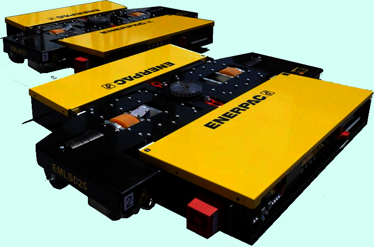
Enerpac Heavy Lifting Technology has expanded its E-mover skates portfolio with the introduction of the Tandem E-Mover EMLSD25. Operating in tandem pairs, the E-movers are synchronised into a single coordinated system for moving and positioning heavy and bulky loads in confined, low-clearance environments.
At the core of the new E-mover is Enerpac Sync-Drive technology. It utilises a camera-based 360° angle and lifting stroke detection alongside real-time, inter-unit communication across up to four E-Mover EMLSD25s, allowing the E-mover skates to communicate and operate as a unified, highly coordinated transport platform.
“The E-mover EMLSD25 skate enables safe, precise horizontal positioning of large, bulky equipment within confined industrial environments with unmatched control and safety,” says Carsten Daft, Senior Product Manager, Enerpac Heavy Lifting Technology. “Capable of scaling capacities up to 800 kN (80 tons), the integrated E-mover skate features a compact chassis housing drive, steering, lifting, control electronics, and efficient lithium battery power management.”
Advanced Operator Control
The EMLSD25 skate incorporates an integrated 70 mm hydraulic lifting cylinder, enabling operators to safely lift and align loads without high-risk vertical lifting. The remote-control interface features a high-visibility colour display providing live telemetry, including real-time sensor values, load balance, traction, lifting height, and system diagnostics. Battery-powered, the zero-emission EMLSD25 operates quietly with approximately four hours of runtime and fast-recharge capability.
The complete Enerpac E-Mover EMV80SD system includes two E-Mover EMLSD25 skates, two MLSR20B100 follower skates and two remote controls. Operators have the option to use either a single E-mover for smaller jobs up to 500 kN (50 tons) or synchronise both E-movers to increase capacity up to 800 kN for larger, bulkier moves. When using two E-movers, the second remote control provides a monitoring and safety function, for example, when the load obscures the view of the main remote control operator.
Precision Manoeuvrability
Preset functions align multiple E-Movers to a shared coordinate system enabling synchronised tandem movement. In addition, lifting controls are integrated with movement controls for safe incremental raising or lowering of loads with continuous monitoring feedback.
Equipped with dual electric drive motors, gearboxes, and multi-steering modes including zero-radius turning, carousel, crab, and dual-axis steering the EMLSD25 skate can navigate restricted workspaces with extreme precision. Safe operation is built in. Shared safety logic continuously monitors the EMLSD25 skate operating parameters, issuing automatic warnings or halting movement if parameters are exceeded.
For more information on the Enerpac E-Mover EMV80SD system, visit www.enerpac.com
 

From predictive maintenance to Agentic AI: Industry explores the next step in intelligent maintenance

Detecting Power-Supply Problems Before They Cause Industrial Control-System Downtime

By Steven Zhang, Product Manager, Powernexu Technology Co Limited

Power-supply failures in industrial control systems are often treated as sudden events. In practice, many failures develop gradually through rising temperature, ageing components, restricted airflow, increasing load or deteriorating connections.

For maintenance teams, the challenge is identifying these warning signs early enough to act before a power problem stops a PLC, industrial PC, I/O system or communications network.

The power supply should therefore be treated as a maintainable asset rather than a component that is replaced only after failure.

Temperature Is Often the First Warning Sign

Heat accelerates stress on many PSU components, including electrolytic capacitors, semiconductors, connectors and cooling fans.

A rising PSU temperature does not automatically mean failure is imminent, but a change from the unit’s normal thermal pattern can be useful maintenance information.

Engineers should monitor the actual air temperature entering the PSU rather than relying only on the temperature of the room or control cabinet.

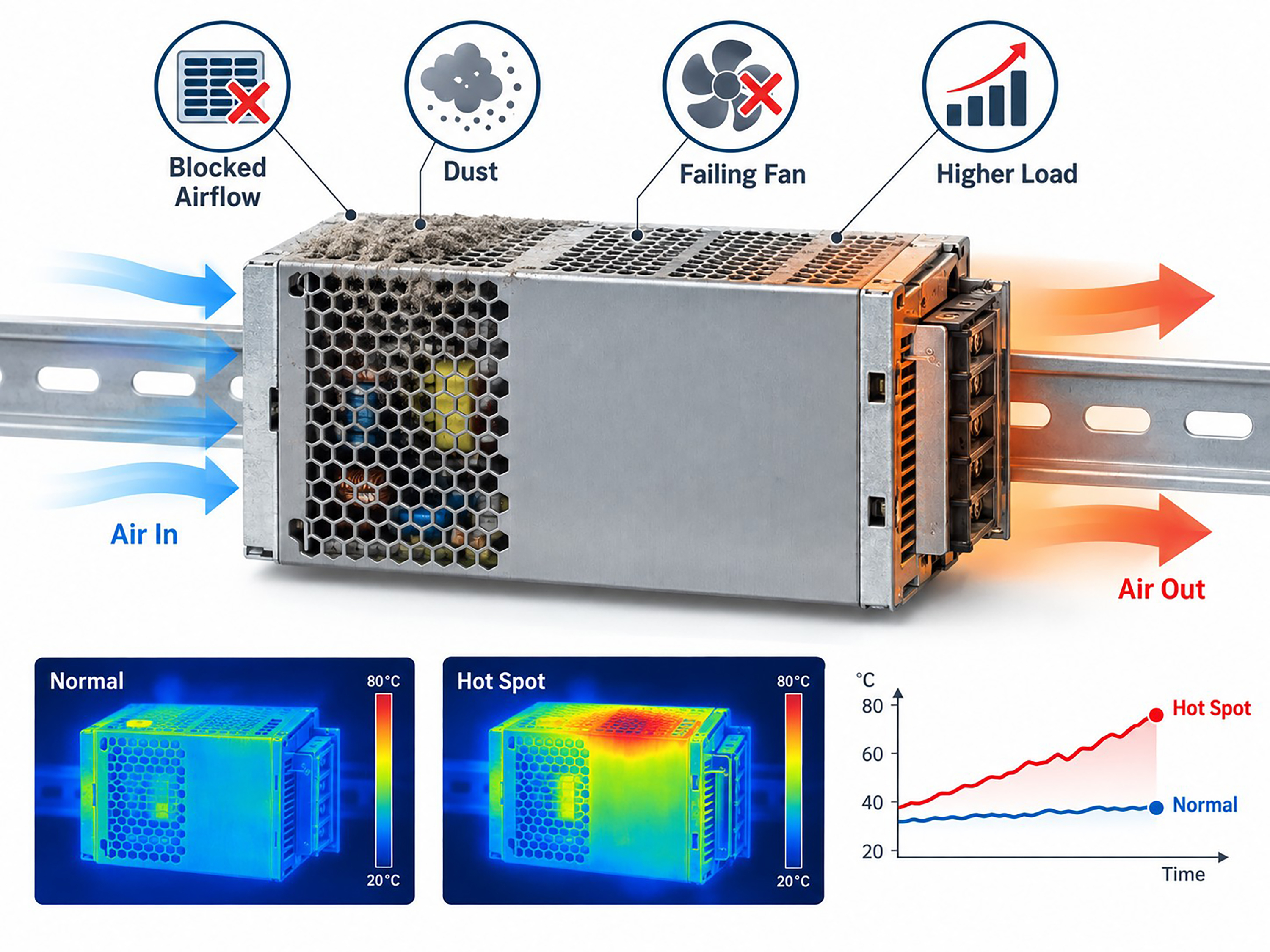
Blocked filters, dust accumulation, failed fans and cable congestion can all reduce effective airflow.

Thermal imaging can also help identify unusually hot connectors, terminals or sections of the power supply.

Figure 1 industrial psu thermal warning signs

Figure 1 – Industrial PSU Thermal Warning Signs

A useful maintenance practice is to compare temperatures under similar machine loads. A PSU that operates noticeably hotter than it did several months earlier may deserve further inspection even if its output voltage is still within specification.

Load Growth Can Reduce Reliability Margin

Industrial systems rarely remain unchanged throughout their lifetime.

Additional sensors, I/O modules, communication devices, industrial PCs or auxiliary equipment may be added without reviewing the original power budget.

The PSU can therefore move gradually from moderate utilisation toward continuous high load.

This reduces the available margin for:

  • Startup current
  • Temporary overloads
  • Higher ambient temperature
  • Component ageing
  • Future expansion

Maintenance teams should periodically compare actual current or power consumption with the PSU’s rated capability and the manufacturer’s derating limits.

A supply that was comfortably sized when the machine was commissioned may no longer have the same margin several years later.

Voltage and Fault Trends Can Reveal Developing Problems

A single output-voltage measurement provides only a snapshot.

Trend information is much more useful.

Where monitoring is available, engineers should watch for changes in:

  • Output voltage
  • Output current
  • PSU temperature
  • Fan speed
  • Input voltage
  • Warning or fault status
  • Redundancy status

Repeated undervoltage warnings, temperature alarms or brief protection events should not simply be cleared and forgotten.

They can indicate increasing load, poor cooling, unstable input power or a developing PSU problem.

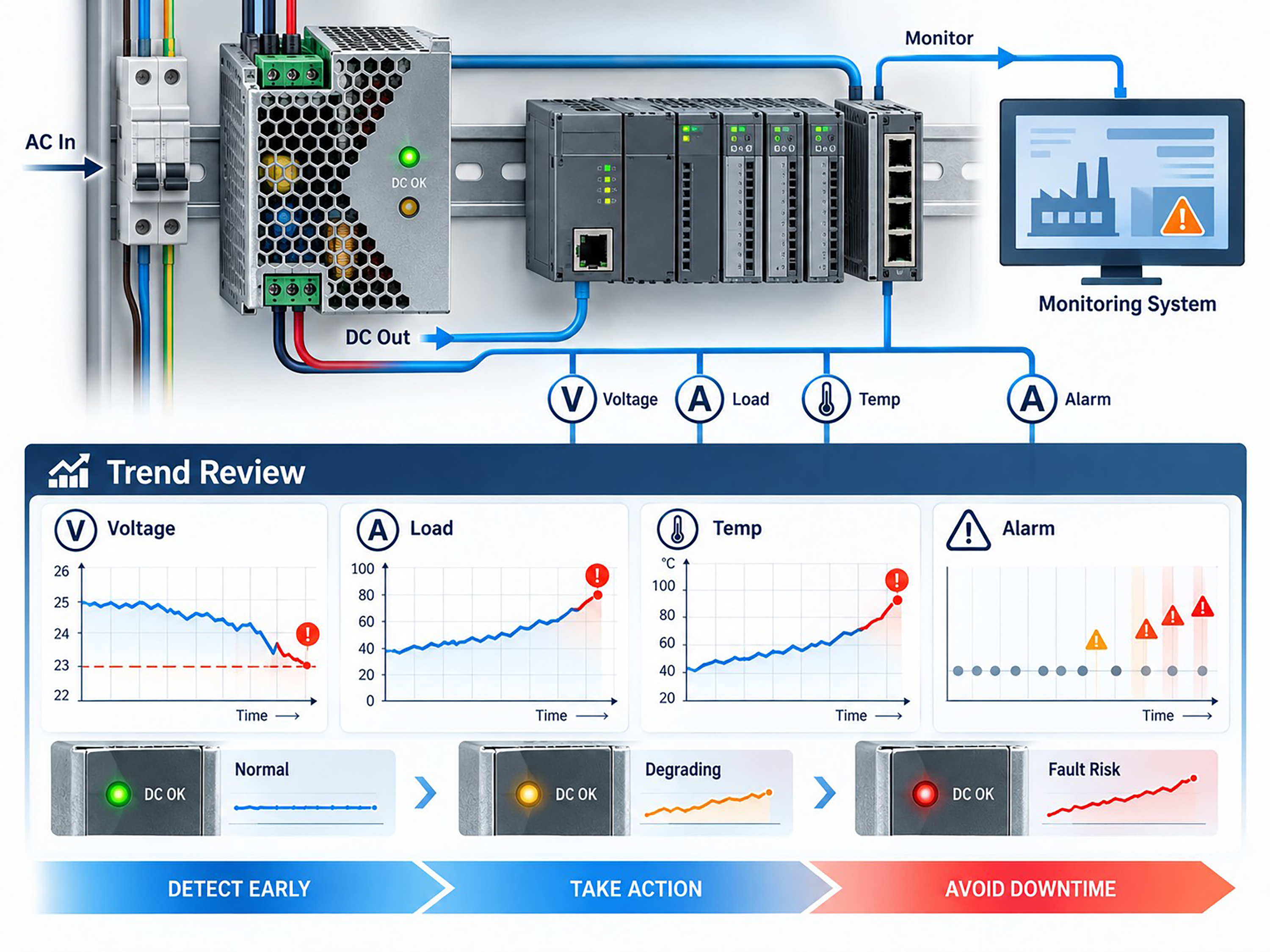
Modern digitally managed supplies may provide telemetry through interfaces such as PMBus, while simpler industrial PSUs may provide DC_OK, alarm contacts or status signals.

Even basic signals become valuable when maintenance teams record and trend them over time.

Figure 2 industrial power monitoring dashboard

Figure 2 – Industrial Power Monitoring Dashboard

Connections Deserve Attention Too

Not every “power-supply failure” originates inside the PSU.

Loose terminals, oxidised contacts, damaged connectors and poorly terminated cables can increase resistance and create local heating.

At higher current, a small resistance increase can produce significant temperature rise.

Inspection should therefore include the complete power path:

AC input → PSU → distribution terminals → DC cabling → control equipment

Discolouration, damaged insulation, unusual connector temperature or repeated voltage drop under load can all indicate a connection problem.

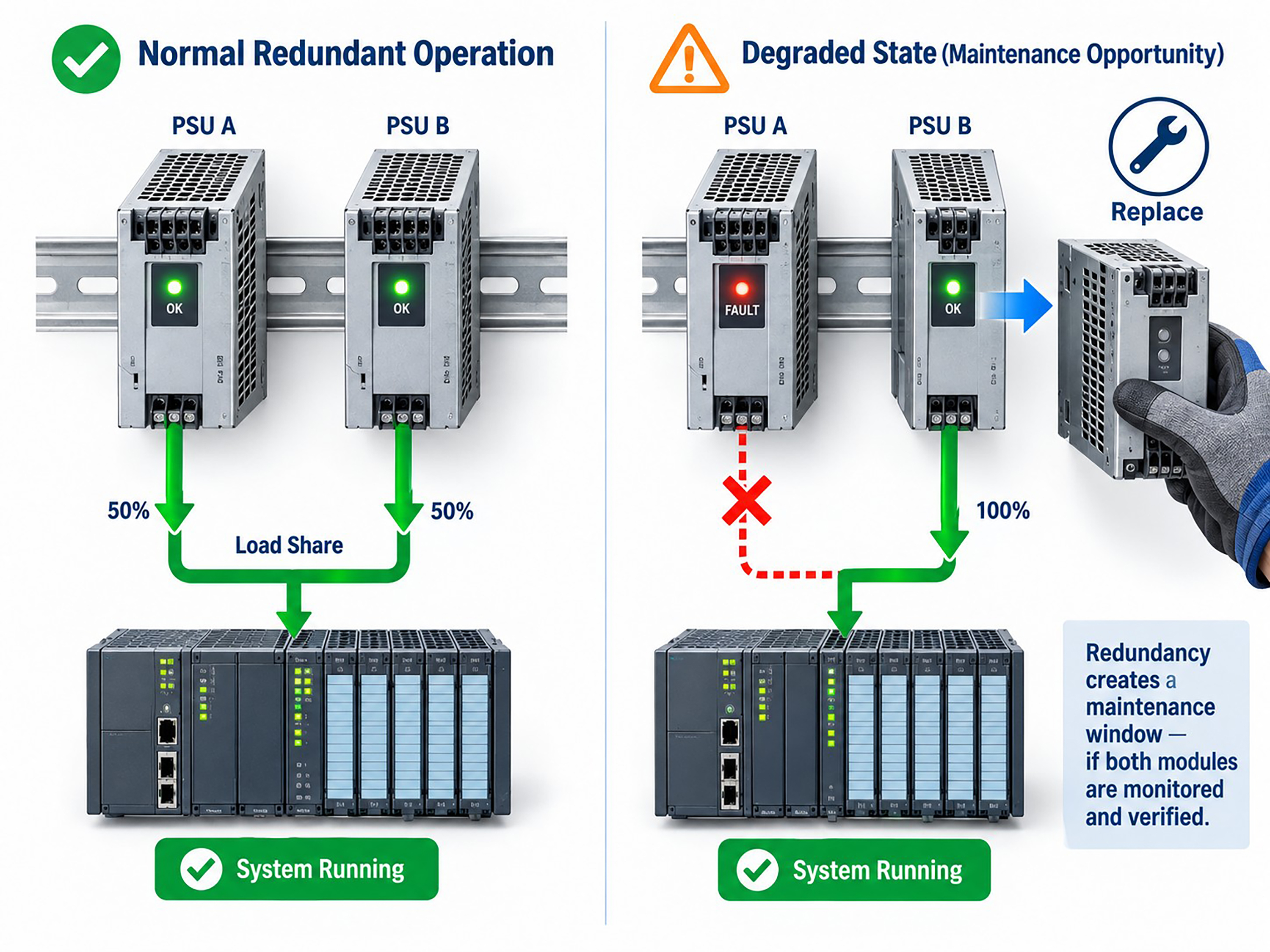
Redundancy Creates a Maintenance Opportunity

Redundant power architectures can reduce downtime, but only if both power paths are healthy.

A common risk is that one redundant PSU fails silently or remains in a warning state while the system continues operating normally on the remaining unit.

The apparent redundancy has then disappeared.

Maintenance teams should periodically confirm:

  • Both modules are online
  • Current sharing is reasonable
  • No persistent fault is present
  • Both input feeds are available
  • Hot-swap replacement works as intended

When redundancy is healthy, a deteriorating PSU can often be replaced during planned maintenance without shutting down the control system.

Figure 3 redundant power supply maintenance workflow

Figure 3 – Redundant Power Supply Maintenance Workflow

Move From Reactive Replacement to Condition-Based Maintenance

The goal is not to replace power supplies unnecessarily.

It is to combine simple indicators—temperature, load, voltage, alarms, airflow and connector condition—to identify units whose operating behaviour is changing.

A practical maintenance routine can include:

  • Periodic thermal inspection
  • Cleaning filters and airflow paths
  • Recording PSU load
  • Reviewing alarms and telemetry
  • Checking redundant modules
  • Inspecting high-current connections
  • Planning replacement when multiple warning indicators appear

Power supplies are critical to every electronic control system, yet they are often ignored until a failure occurs.

By monitoring how a PSU behaves over time, maintenance teams can turn many power failures from unexpected production events into planned service activities.

Author Bio

Steven Zhang is Product Manager at Powernexu Technology Co Limited, focusing on server and industrial power supplies, redundant power architectures and power-system integration. His work covers power-delivery reliability, thermal performance and high-density computing and industrial control applications.

Company: Powernexu Technology Co Limited
Website: www.powernexu.com
Email: This email address is being protected from spambots. You need JavaScript enabled to view it.

CMMS RADIO ALL THINGS CMMS


BCAS shines a light on compressed air careers with the launch of On Air

The British Compressed Air Society (BCAS) has launched On Air, its new compressed air industry awareness campaign.

On Air will be encouraging young people to consider a rewarding career in the industry, through apprenticeship schemes, graduate opportunities, or by switching from a related industry sector.

Ashley Quartermann, Executive Director at BCAS explained:

“The engineering sector is facing a recruitment challenge. An ageing workforce, coupled with new workplace challenges, as the demand for hybrid working arrangement continues to grow, is resulting in a shortage of skilled engineers, technicians and service professionals.  

“According to Engineering UK, 6.3 million people work in engineering roles, around a fifth of the UK workforce, and employers are competing hard to recruit and retain skilled engineers, technicians and apprentices.

“For the compressed air industry, these challenges are felt even more keenly. An essential, yet often unnoticed utility used in virtually every industry, many young people starting out on their career path are unaware of the opportunities that exist in the sector.

On Air is the compressed air industry’s response to this recruitment challenge. The vibrant and youthful campaign is set to celebrate everything that is good about the sector; the opportunities to learn, to travel, to specialise - through social media engagement, engineering influencers and a dedicated microsite.”

Historically, engineering service organisations have emphasised technical competence and long service, whereas newer recruits often value rapid development, varied experiences, and visible career progression. 

And for many, site-based work is preferable, providing immediate impact where work physically improves a product or process alongside tangible problem solving.

Including apprentices, graduates and career changers, On Air will be championing the wide variety of career opportunities available and celebrating the extensive range of applications and industry that compressed air impacts. From formula one to aerospace to medical research. The outdated image of a noisy factory environment with the constant hiss of compressed air pipework leaks is moving aside for a new generation of intelligent compressed air installations, driven by data.

In conjunction with the launch of On Air, BCAS has also created a new committee for 18–40-year-olds working in the industry.

With representatives from across the BCAS member network, the 22-strong committee will be focusing on key topics including attraction into the industry, retention of young talent, and the ongoing lack of awareness of compressed air as a career path. Acting as an advisory voice to BCAS Board members, the new committee will be instrumental in helping to shape the future direction of career paths and training in the sector.

To learn more, visit [https://.onair.bcas.org.uk/]https://onair.bcas.org.uk/ or follow us on social media:

This website is owned and operated by: MSL Media Limited

msl logo
www.mslmedialtd.com

Co. Number: 05359182

© 2005 MSL Media Ltd. All rights reserved. E&OE

ems logo mobile