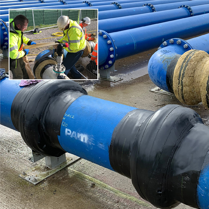
As part of United Utilities water quality improvement programme, JMC North West Ltd, on behalf of NMCN, recently completed works to bury the above ground timing loop at the Pex Hill Service Reservoir. The challenge was to provide a durable, reliable corrosion prevention solution to protect over 90 double flanged joints prior to full encapsulation. To provide this high level of protection, JMC North West Ltd turned to Winn & Coales (Denso) Ltd for their services.
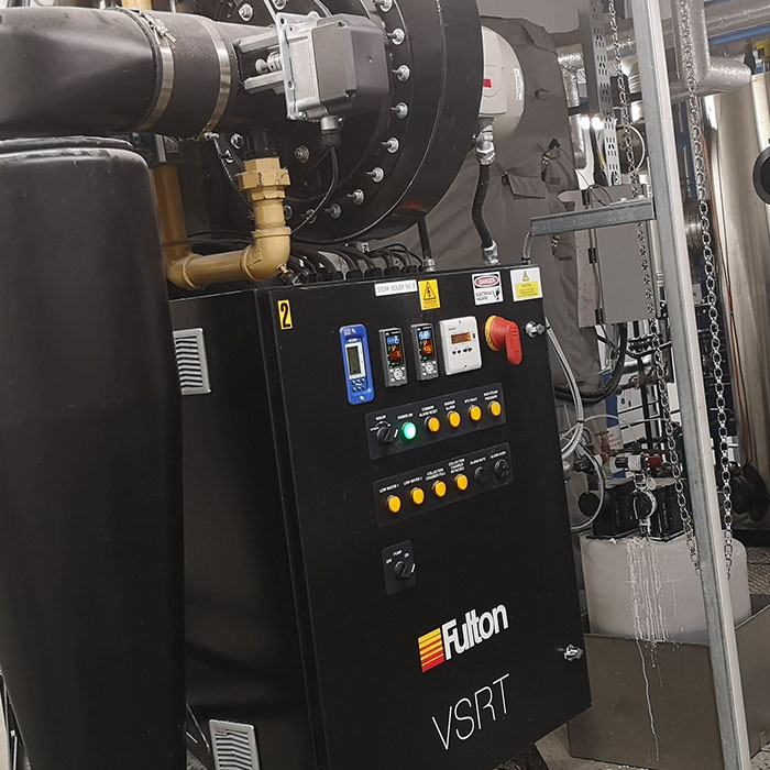
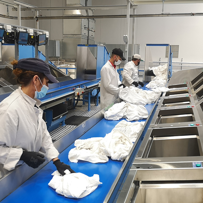
Having moved from a facility that was too small and would have been uneconomical to upgrade, the overriding requirements for Elis’ new, state-of-the-art Southampton-based facility were to increase and future-proof throughput by increasing capacity as and when required. Protecting their investment was also paramount, so manufacturer-backed aftercare solutions were also key to the long-term plan.
The existing facility used a combination of indirect steam from a horizontal steam boiler and steam-heated ironers and dryers during the laundry process. But with the new multi-service flat linen plant – which services the Southern region hospitality and healthcare industry – came a new approach for Elis and, because the company processes laundry for the healthcare sector amongst others, they instead opted for a heat transfer system that would pre-heat water for the washing machines to a minimum of 72 degrees centigrade by directly injecting steam into the water supply.
 The process of extracting and processing uranium can present many challenges. Machinery and equipment are exposed to environments during production, which over time can cause damage and lead to shutdowns.
 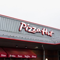 A nationwide project to upgrade Pizza Hut’s kitchen ventilation systems to a higher performing, energy efficient solution is underway. Project manager Marcus Sawkins of GFMS Services Limited has already upgraded several of the restaurants’ systems with the Elta Fans QUBE Centrifugal Box Fan which is reducing energy usage. The most recent installation was at Royale Leisure Park in London where the new Elta Fans QUBE solution has reduced energy costs by up to 10%+ and breakdowns occurring on a regular basis, to zero.
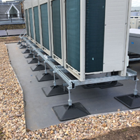 Big Foot Supplies Custom Support for Acoustic Screening
 Stackable 3D printers may hold the key to a faster yet more cost-effective design and manufacturing process. But what is stackable 3D printing? And how does it work to benefit businesses and meet their printing needs? To answer these questions, CEL has released a new white paper, ‘