By Paul Uher and Ernesto Wiedenbrug, Ph.D.
Everybody who is responsible for maintenance of VFDdriven application knows the feeling… The application was running well, and now it acts up and trips sometimes, and the drive’s trip message isn’t much help. Now what?
This paper discusses such a case, and how being able to see the dynamic interaction of voltage level and frequency changes led to the solution.
Situation:
Paul Uher from SKF Industrial Market in Sweden was called into a major bearing manufacturing plant to offer service for a VFD-driven application that was causing problems.
The drive is a 400V 30hp manufactured by Danfoss, and the load is an eccentric press which creates the rollingelements for bearings. Paul’s customer had explained that the application worked well for about two hours and then it started slowing down, finally coming to a stop, even though no changes were being made on the load-side.
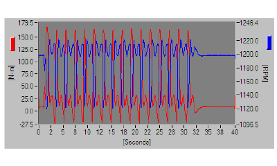
Torque and Speed vs. Time
Frequency and Voltage vs. Time
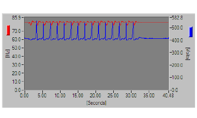
Figure 1: Torque, speed, frequency and voltage level vs. time during healthy operation.
Action:
This description clarified that the problem had to be in one of two spots: Eitherthere was something wrong with theexternal control signals/programming tothe drive, or the issue was internal, in thedrive control itself. In order to answerthe question as to which of thesealternatives was causing the slow-down,it was necessary to get “eyes” onto whatwas happening. Obtaining a clear pictureof dynamic VFD application problems likethese is only possible by seeing howfrequency variations, voltage levels,torque requirements and motor speedinteract with one another. This is what
the software component VFD4000 delivers for the SKF Dynamic Motor Analyzer - EXP 4000. Fig. 1 shows these four traces for 40s of healthy operation, where fifteen 2s cycles of the eccentric press are followed by a short no-load period.
The application started to slow down after roughly two hours of successful operation. The difference in the healthy signature of Fig 1 is apparent in the frequency and voltage vs. time plot in Fig 2. The traces show that the voltage ramps down towards the end of each stroke of the eccentric press, while the drive tries to maintain a constant frequency until it shuts down for a very brief instance.
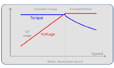
Figure 2: Frequency and voltage vs. time during faulty operation.
Volts per Hz:
One control technique internal to VFDs is called “Volts per Hertz” [1]. It means that voltage level gets changed in proportion to the frequency changes for frequencies below nameplate, as shown in Fig 3. In other words, if the motor runs at half nameplate frequency, it should be supplied by half nameplate voltage. A Volts per Hertz control typically doesn’t raise the voltage level above nameplate for frequencies higher than the nameplate frequency of the motor. This type of control has the ability of delivering full torque for the low speed range, and full nameplate power for the speeds above nameplate – at the expense of dropping torque capabilities in the high-speed region.
Even if a drive had a different control strategy than V over f, this rule of thumb will still apply for applications that have relatively small frequency changes as is the case being analyzed here. The voltage and frequency vs. time traces of Fig 2 show that there are times where the expected normal behavior of the drive falls apart: voltage level ramps down while the drive attempts to maintain constant frequency output. This answers the question – the problem is originating internally in the VFD.
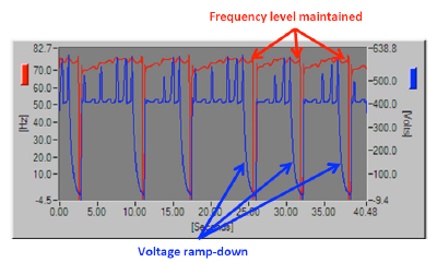
Figure 3: Voltage level and torque vs. speed for V/f control.
Correction:
Since now it was clear that the problem somehow originated internally in the drive, and wasn’t caused by the external control signals, the next step was to approach Danfoss application support and ask for help. The VFD manufacturer’s application engineer was able to diagnose the issue by looking at the voltage, torque, speed and frequency plots vs. time of healthy operation and during the slow-down. The problem was that the eccentric press required a very high peak torque to manufacture this particular batch of rolling elements. Over time the motor started heating up, causing the stator resistance to rise – ultimately starving the magnetic flux and the torque-generation capability.
The solution was described in an application note that was emailed by the Danfoss application engineer, explaining which two drive settings needed to be set differently to shift the drive from the default high-efficiency settings towards peak torque settings that this application required [2].
Results and Conclusion:
Changing the two parameters in the VFD setup as suggested by the Danfoss application engineer solved the issue upon first try. The eccentric press has been working reliably ever since.
This case study shows how VFD applications can introduce unique complexities never offered by line-operated motor applications. The voltage level and frequency vs. time traces were key to diagnose the root cause problem being in the drive control. That data, together with the torque vs. time plots were the information that allowed the Danfoss application engineer to diagnose the issue, and realize the simple solution. The “VFD Details” plots of the VFD4000 gave eyes to the maintenance engineer, allowed him to isolate the problem, and gave eyes to the VFD application support to solve the issue.
References:
[1] “Application Guide for AC Adjustable Speed Drive Systems.pdf”, pg. 14, NEMA 2007.
[2] “Instruction Manual – VLT 5000”, Danfoss.
For further information, please visit http://www.whitelegg.com
