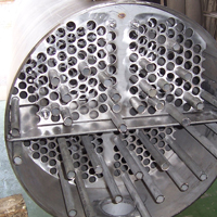
 Since its inspection, shell and tube heat exchangers have proven to be the most robust heat transfer equipment. Since the industrial revolution, heat exchangers have been a necessity in terms of harnessing and distributing energy.
In 1923 the world saw the introduction of the first commercially-available plate heat exchanger by Dr Richard Seligman, founder of APV, though the original idea was patented in the latter part of the 1800’s. Plate heat exchangers rose to popularity, due to its cost-effective nature – particularly in the 1970’s in the face of the energy crisis. Developed during an era of industrial progress, plate heat exchangers could be mass produced on the production line courtesy of Henry Ford.
Unlike the plate heat exchanger, the shell and tube exchanger has to be custom designed and built for each application. This makes the shell and tube exchanger costly to produce and as such has lost market to the cheaper, plate exchanger alternative.
However, the shell and tube remains the most robust and maintainable of the heat exchangers and retains the monopoly in the refinery industries as they provide a high-fidelity solution to a high-risk and pressure application. Thanks to a possibility of double tube sheet designs, which removes the possibility of fluids mixing, the shell and tube exchanger has retained application in the hygienic and pharmaceutical industries.
Though not common, shell and tube heat exchangers are sensitive to flow-induced vibrations and if not properly accounted for can cause tube failures in the heat exchanger.
According to TEMA (Tubular Exchanger Manufacturers Association) standards as laid out in their latest edition; “The fluid flowing inter relate with heat exchanger geometry and can cause heat exchanger tubes to vibrate. This phenomenon is highly complex and the state of the art is such that the solution to this problem is difficult to define. Due to the complexity of the problem, the TEMA guarantee does not cover vibration damage.”
There are three main types of vibration mechanisms; Vibration Fluid-elastic Instability, Acoustic Vibration, and Vortex Shedding which affects the frequency mode damages caused. As detailed by TEMA (8th Edition, page 95, V-2), mechanical failure of tubes resulting from flow-induced vibration may occur in various forms and damage may result from any of the following independent conditions, or a combination of the following:
- Collision damage from the impact of tubes against each other or the vessel wall, due to large amplitudes of the vibrating tube. The tube wall eventually wears thin, causing failure.
- Baffle tube holes are also susceptible. Baffle tube holes requires a manufacturing clearance over the tube outer diameter to facilitate fabrication. When large fluid forces are present, the tube can impact the baffle hole causing thinning of the tube wall in an uneven manner.
- Tube sheet clamping effect; tubes may be expanded into the tube sheet to minimise the crevice between the other tube wall and tube sheet hole. The natural frequency of the tube span adjacent to the tube sheet is increased by the clamping effect.
- Flaws contained with the material and strategically oriented with respect to the stress field can readily propagate and actuate tube failure.
- Acoustic vibration and resonance is due to the gas column oscillation and is excited by phased vortex shedding. The oscillation creates an acoustic vibration of a standing wave. The generated sound wave will not affect the tube bundle unless the acoustic resonant frequency approaches the tube natural frequency. When the acoustic resonant frequency approaches the tube natural frequency, any tendency towards tube vibration will accentuated with possible tube failure.
As cited by Exxon Mobile at the NPRA Maintenance and Reliability conference (2011), tube damage from flow-induced vibrations has increased over the years. “This is primarily as a result of advances in catalyst and control technologies which allow operators to increase plant capacity by simply increasing the flow through existing process equipment. In addition, new exchanger designs are smaller which entails greater shell-side velocities.”
Predicting tube failure is a crucial step in the design process, but accurately forecasting vibration is the most challenging of all. Current predictions of vibration failure are still complex with many factors contributing. The best commercial software still uses simplistic approximations and do not consider all the variables. This is despite newer generation technological advancements. Engineers today have at their disposal Computational Fluid Dynamics (CFD) which enables accurate fluid-flow phenomena prediction, combined with Finite Element Analysis (FEA), which accurately predicts stressors in complex geometries such as tube bundles. Yet failures as a result of vibration are on the increase.
TEMA details that the current state of the art flow-induced vibration correlations are not sophisticated enough to warrant treating the multi-span tube vibration problem (or mode shape other than the fundamentals) in one comprehensive analysis. Therefore, the potential for vibration is evaluated for each individual span, with velocity and natural frequency conserved being that of the unsupported span under examination.
According to JM Chonoweht, Flow-induced Vibration, Heat Exchanger Design Handbook, (1983), when comparing post-tube failure predictions of actual data from the HTFS Data Book, correct predictions were made for 48 of the 67 cases – or 72% correct. Of the cases with no vibration reported only about 50% were predicted correctly.
This substantiates the claim of Ignatius Herbst*, M.Eng (chemical), managing director of Logichem Process Engineering and Projects in South Africa, that the model of calculations is only as strong as the input data provided by the engineer. “It is interesting to note from the above quote, that only once the tubes were investigated thoroughly post failure, were better predictions made,” says Herbst.
One contributing factor to inaccurate tube failure predications is the incorrect application of compressive axial load on tubes. According to TEMA (8th Edition, pg 122, V 13-9), “The heat exchanger designer must recognise the potential adverse impact on vibration by compressive axial loading of tubes due to pressure and/or temperature conditions. This is particularly significant for tubes in single pass, fixed tube sheet exchangers where the hot fluid is in the tube side, and in all multiple-tube pass fixed heat exchangers. The use of an expansion joint in such cases may result in reduction of the tube compressive stress.”
 |
 |
 |
Figure 1: Tube in compression 9.75Hz. |
Figure 2: Tube no load, 27.02 Hz. |
Figure 3: Tube in tension, 36.70 Hz. |
Case Study
The subject of this editorial is based on a real case faced by Herbst, where compressive axial stress, induced in the tubes as a result of the tube to tube sheet joint, led to incorrect Vibration Analysis and ultimately to limited tube failure.
“TEMA lists three possible tube-to-tube sheet joints methods; Welded; Expanded with and without grooves; Seal welded and expanded. Unfortunately, TEMA does not dictate a mandatory method to follow to avoid or limit the introduction of compressive stress in tubes due to tube-to-tube sheet joint. Therefore, end-users and their engineering partners will often dictate to manufactures how the tubes should be fixed to the tube sheet,” remarks Herbst. “In this case, the end user specified, strength welded and expansion of tubes. Coupled to this, the end user also specified a sequence i.e. weld and then hydraulically expand the tubes. This sequence led to very high compressive stresses in the tubes.”
Why do expanded tube-to-tube sheet joints induce compressive load on the tube? The laymen explanation presented by Herbst:
“When expanding the tube into the tube sheet, the tube expands similar to tubular balloons used by balloon artists. The tube will expand in all directions however the expansion in the length down the axis is more than the increase in diameter. This axial expansion is not a problem during the first joint as the tube is free to expand, however fixing the second joint at the other end followed by its expansion results in axial compressive stress. In the case were the tubes are first welded, both expansions lead to an increased compressive stress.”
“The magnitude of the compressive stress is dependant on the unsupported tube span or Baffle spacing. If long tube spans are used the tubes would bow more profound and the axial compressive stress would lessen. Shorter tube spans result in less bowing but higher stress.”
“HTFS and HTRI, the leading shell and tube design software, includes compressive stress due to operating temperatures and pressure comprehensively, but do not allow for, or calculate the compressive stress induced during the manufacturing process. It is up to the designer to specify any pre-stress conditions. By omitting this compression stress, flow-induced vibration calculations are null and void.”
The cautionary statement Herbst wishes to communicate is that the actual assembly process should be considered when predicting flow-induced vibration.
* Ignatius Herbst is the managing director of South African based companies, Logichem Process Engineering and Logichem Process Projects. The companies service the engineering needs of the pharmaceutical, refinery, distillation and food and beverage industries in Africa, with scope to expand into overseas markets.
For more information, visit www.logichemprocess.com
