
Introduction
Inefficient heat transfer in the convection section of a process heater is readily witnessed by an increase in stack temperature beyond design parameters. The timing and urgency for addressing this situation are related to not only the degree of overheating in the stack but also product demand, economics, and fuel costs.
This article will discuss Tube Tech’s, an Integrated Global Services (IGS) solution, approach to restoring heat transfer efficiency of fired heater furnaces and the results achieved at an Egyptian oil refinery.
Part One: Inspection and Technical Evaluation
For many IGS Tube Tech projects, a site visit is made to complete an inspection of the convection section and to collect current operating data so that an evaluation can be conducted. The evaluation determines the baseline operating conditions and estimates the potential project scope and expected benefits.
The evaluation is based on calculating the external fouling resistance factor for each bundle in the convection section based on the process data. The factors will be relieved by cleaning and a further evaluation would determine the post-cleaning performance, based on a constant processing duty, for example. The IGS Tube Tech cleaning technology allows for more than 90% of all the tube and fin surface area to be treated, unlike other more conventional methods which reach only 20% to 40% of the tube surfaces, depending on configuration.
Part Two: Project Planning & Execution Approach
To perform an effective clean using a unique Remotely Operated Vehicle (ROV) and protect the existing equipment from water exposure, the following five steps are considered for each project (figure 1):
Figure 1. The Tube Tech Solution
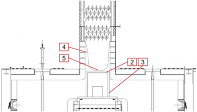
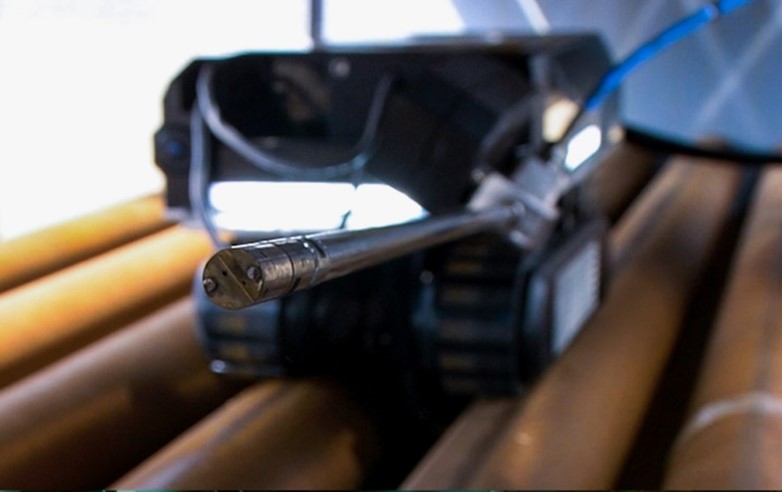
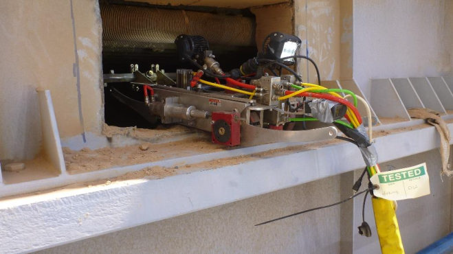
The ROV is designed to fully clean convection bank coils by penetrating its lance deep between tube rows. The technology removes more than 90% of fouling from all convection bundles. No refractory is damaged since the ROVs are programmed to direct a high-pressure medium to the tubes only. All activities typically can be completed in 72-120 hours (three to five twelve-hour shifts).
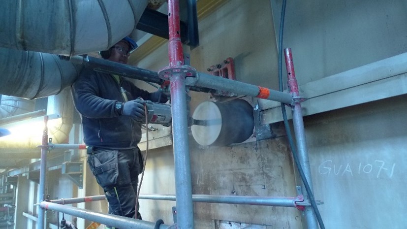
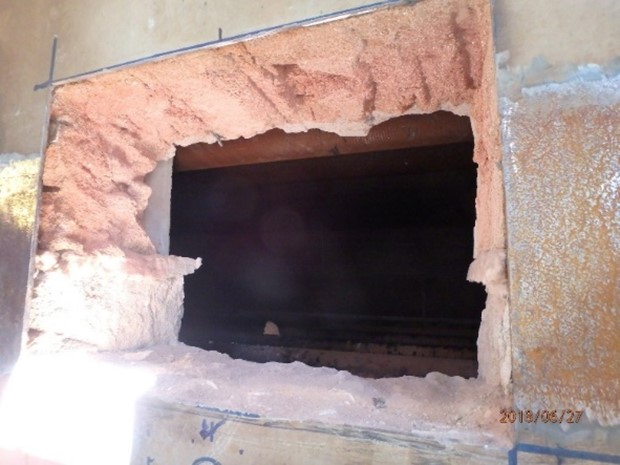
Figures 2&3. The external casing in this instance is cut to create 350 mm openings
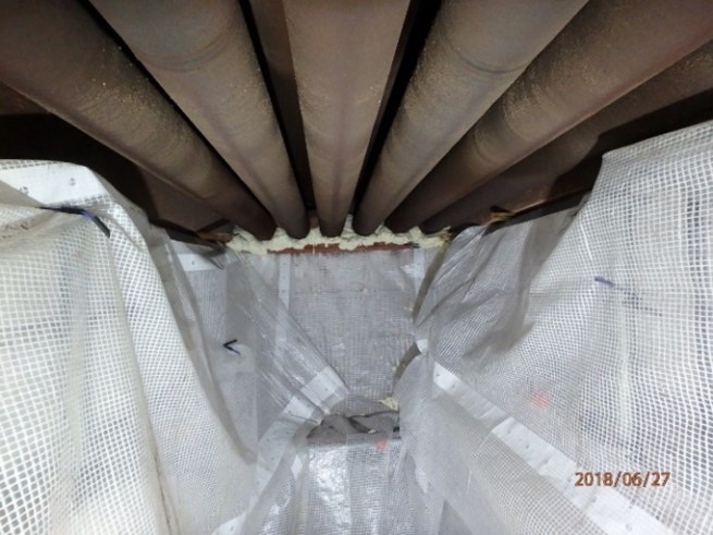
Figures 4&5. Plastic tarpaulin at the bottom of the convection section and the ROV on the top of the bundle.
Part Three: Post-Project Benefit Analysis.
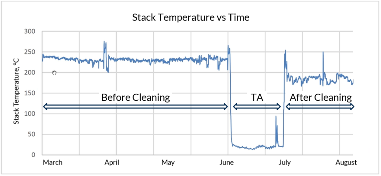
In many cases, the stack temperature is determined to be a key performance indicator to identify and quantify the benefit after cleaning. To illustrate the benefits, we will review a recent project, referred to as project x. On completion of project x a sizeable benefit of 40°C in stack temperature reduction was achieved. The plant also reported an average increase in overall fuel efficiency from 89.5% to 91.5%,leading to 2 MW less heat loss to the stack under the same operating capacity. The customer reported a payback period of less than four months.
Figure 6. Stack Temperature Before and After Cleaning
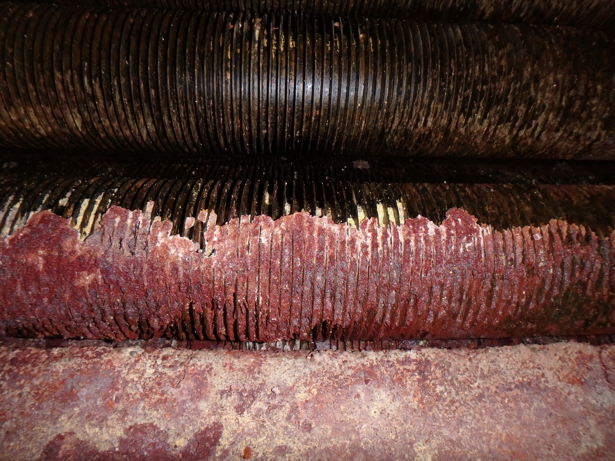
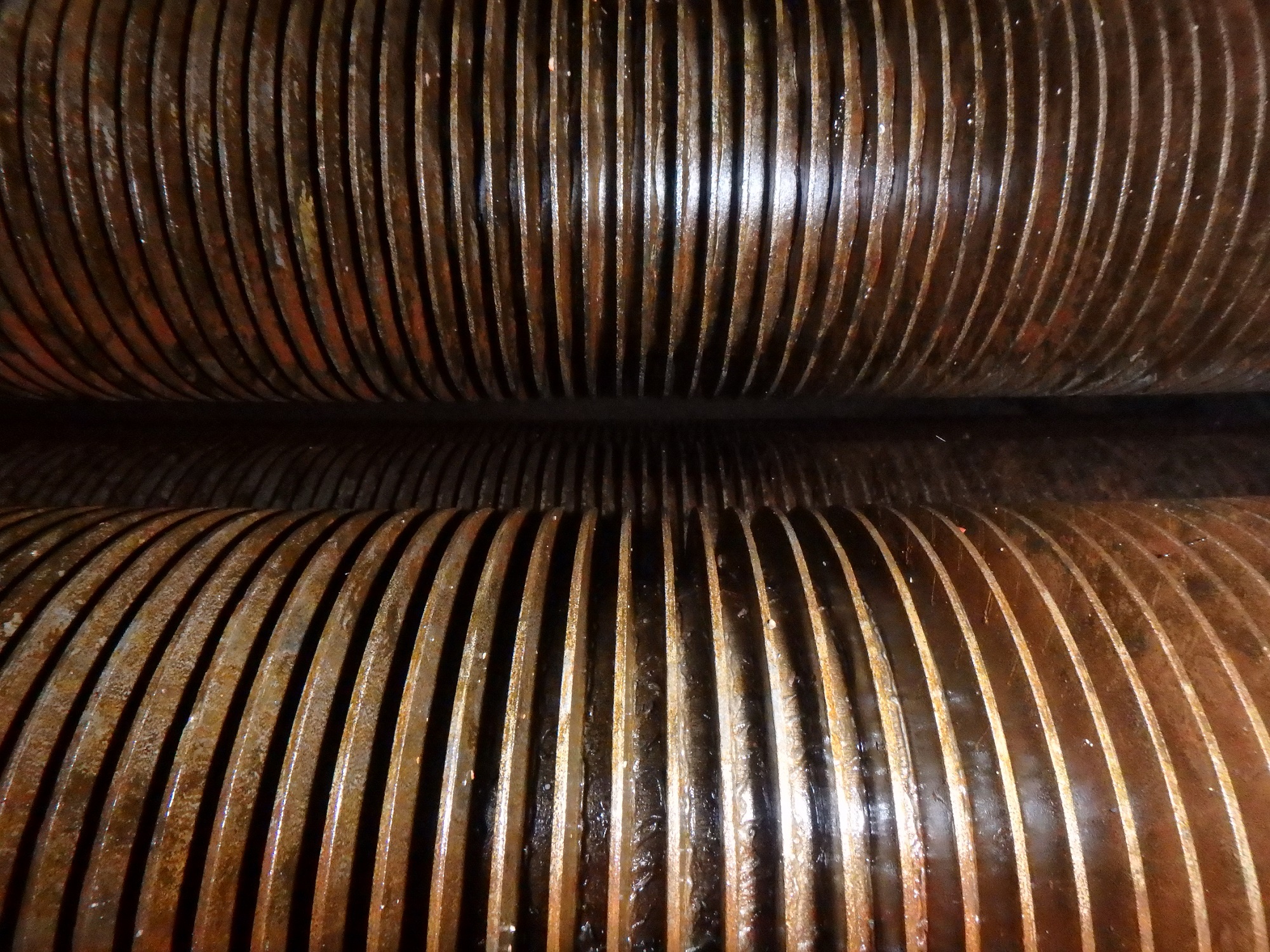
Figures 7&8. Before and After Cleaning -Part One
Part Four: Acknowledgements and New Data Two Years After Cleaning
A balanced heat distribution between sections is crucial in coking-sensitive services. Keeping the convection section surface clean not only helps to save fuel and increase steam generation but also positively influences the steam cracking process. The achieved benefit on project x was 16,000 MWh/year fuel savings and 2500 tons annual CO2 reduction (fuel is CH4/H2 mixture).
After almost two years, the client reported a slight elevation in stack temperature of 10 °C and a stable efficiency increase of 1.5%. The next clean is anticipated to take place after sixyears to reinstate the efficiency. To ensure the obtained benefit is long-lasting, IGS also recommends a combination of the Tube Tech ROV cleaning with Cetek’s proprietary ceramic refractory coatings to protect and encapsulate the ceramic fiber and stop refractory deterioration and new fouling formation on the outside surface of the convection tubes.
Part Five: Example of Tube Tech ROV Cleaning – Ethylene Furnace
IGS was provided with furnace configuration and process parameters for each bank of the convection section of this ethylene furnace. The objective was to keep the process duty and thus, the coil outlet temperature the same and compare scenarios before and after.
It is worth mentioning that these furnaces were designed to have 68.3% to 71.0% process duty of total absorbed duty (depending on whether it is SOR or EOR), and if, for example, steam superheating coils are fouled, cleaning may reduce this ratio process/total duty. An additional indicator of this potential fouling consequence is the fact that almost no BFW is being used for attemperation (desuperheating). For this scenario, constant flow rates for process streams are assumed, but it is also possible to consider all the factors and heat balance changes for the entire system.
Table 1. Convection Section Cleaning Results for Ethylene Cracker.
|
Parameter |
UOM |
Before |
After |
|
Fuel Firing |
nm3/hr |
5565 |
5655 |
|
Fuel Firing** |
Gcal/hr (LHV) |
32.04 |
32.64 |
|
Total Absorbed Duty |
Gcal/hr |
29.37 |
30.56 |
|
Radiant Duty |
Gcal/hr |
14.86 |
15.02 |
|
BWT |
°C |
1033 |
1037 |
|
Stack Temperature |
°C |
180 |
134 |
|
Radiant Inlet |
°C |
590 |
582 |
|
CSS Outlet |
°C |
376 |
454 |
|
HSS Outlet* |
°C |
446 |
541 |
|
BFW Outlet |
°C |
269 |
254 |
|
Overall Efficiency |
% |
91.67 |
93.61 |
|
Process Duty |
Gcal/hr |
21.21 |
21.21 |
|
Steam Duty |
Gcal/hr |
8.16 |
9.35 |
*HSS coil has been evaluated assuming no BFW for desuperheating
** 1.5% of Heat Losses have been assumed, and 11% of Excess Air is calculated using the flue gas oxygen content.
Part Six: Example of Tube Tech ROV Cleaning - CCR Platforming Heater
In configurations where a steam generator is only located in the convection section, such as platforming heaters, it is crucial to adjust flow rates and reflect changes in absorbed duty for each bundle that may result from cleaning. Specifically, a steam drum should be included in the model to respond accurately to all changes in temperatures/pressures of inlet/outlet streams.
The following convection section reflects the most widespread design with the following bundles (from top to bottom): Economizer, Upper Steam Generation, Steam Superheating and Lower Steam Generation. (Example under the same firing rate).
Table 2. Convection Section Cleaning Evaluation Results for CCR Platformer Heater
|
Parameter |
UOM |
Before |
After |
|
Stack Temperature |
°C |
208 |
168 |
|
Fuel Efficiency |
% |
88.32 |
90.38 |
|
Absorbed Duty |
Gcal/hr |
13.8 |
14.8 |
|
BFW Inlet Temperature |
°C |
122 |
122 |
|
BFW Mass Flow |
kg/hr |
22203 |
23886 |
|
Mass Circulation Through Steam Generator |
tonne/hr |
150 |
150 |
|
Steam Drum Pressure |
kg/cm2_g |
36.2 |
36.2 |
|
Blowdown Amount |
% |
5 |
5 |
|
Total Amount of Produced Superheated Steam |
kg/hr |
21146 |
22748 |
|
Superheated Steam Temperature |
°C |
360 |
362 |
Part Seven: Case Study - Revitalizing the Performance of a Refinery's Hydrogen Generation Unit
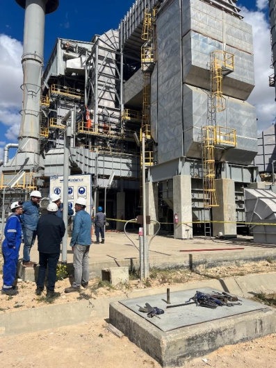
An Egyptian oil refinery, in operation since 1999, has faced challenges with its Hydrogen Generation Unit (HGU) since 2005. Issues such as hot spots on catalyst tubes, ageingreformer tubes and outlet systems, and reduced hydrogen demand have led to the unit operating at a reduced capacity. To address these bottlenecks and evaluate the unit's current status, a comprehensive assessment and debottleneck study was conducted by the OEM.
Key Study Findings
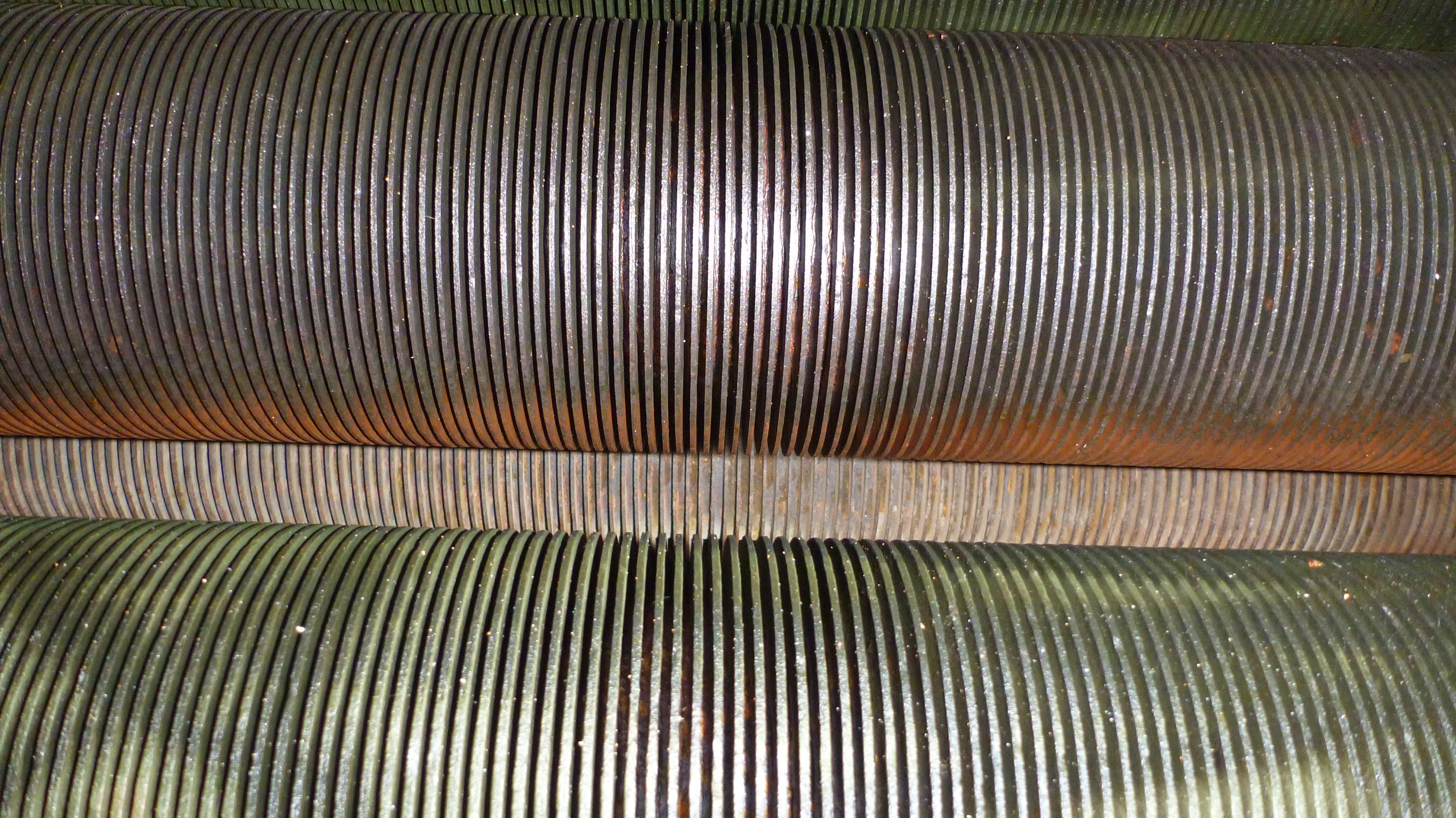
One significant finding of the study revealed the underperformance of the convection coils, which hindered the unit from achieving its desired efficiency. Over more than 20 years of operation, the convection coils, primarily consisting of finned tubes, suffered from increased fouling due to inadequate inspection and cleaning practices. The study recommended a potential solution of inspecting and robotically cleaning the external surface of the finned tubes to overcome this issue.
Project Overview
On the advice of the OEM, Integrated Global Services (IGS) was contracted to perform Tube Tech’s convection section performance recovery service at a hydrogen production unit at the refinery. The project involved increasing the size of six existing access doors in the convection section and the robotic de-fouling of convection coils.
The project commenced on March 29, 2023, and was completed on April 3, 2023. The original planned scope of work, which included de-fouling and door installation, remained unchanged throughout the project.
Case Study Image 1
Safety
Safety is a primary concern for IGS, and a robust safety program was implemented to ensure a safe working environment for all personnel involved. The company maintains a zero-incident safety philosophy and actively promotes a culture of safety among its employees. Daily toolbox talks, safety observations, unit walk-downs, and job safety audits were conducted to mitigate potential hazards and maintain safety standards throughout the project.
IGS has a strong safety track record, with a Total Recordable Incident Rate (TRIR) of 0.0 in 2022, well below the industry average. The company adheres to OSHA best practices and local safety regulations to ensure compliance and maintain a safe work environment.
Quality
IGS follows stringent quality control standards to meet customer requirements. The project was executed in accordance with the IGS quality control standards, and a Quality Control Package (QCP) was agreed upon before the start of work.
Achieved Results
A performance test run was then conducted to evaluate the unit's condition after the cleaning process. The unit's capacity was successfully raised to 100% on April 16 and maintained for 24 hours. The test procedure for evaluating the unit's performance after cleaning was based on the HPU's latest probation test, ensuring consistency and comparability. Data from various sources, including DCS data, laboratory analysis results, outside field/local data, and electrical data, were collected during the test to accurately assess the unit's performance.
Case Study Image 2&3

Test Parameters
The performance test for the HGU was conducted from April 16 at 11:00 to April 17 at 11:00, lasting 24 hours. The main feedstock for the unit was natural gas, supplemented by a small portion of recycled hydrogen. The composition of the natural gas feed, as well as mass flow rates for different streams, was recorded. The laboratory analysis results showed changes in the feed composition and products during the probation test.
Unit Operating Parameters
Various operating parameters of the unit, such as temperatures, pressures, steam-to-carbon ratio, and steam drum pressure, were monitored during the probation test. The unit's performance was compared to previous tests, revealing improved performance in terms of duty recovered by the convection section and a reduction in stack temperature.
Probation Test Evaluation
The evaluation of the probation test results indicated that the cleaning of the convection section had led to a 14% increase in duty recovered from flue gases compared to the previous test in December 2021. The reformer inlet temperature also increased from 437°C to 501°C, contributing to improved thermal efficiency. The lower stack temperature and increased efficiency resulted in cost savings of approximately $220,000 annually.
Case Study Image 4
Case Study Conclusions
The successful cleaning of the convection section in the refinery's HGU unit marked a significant step towards restoring the unit's performance. The removal of fouling from the finned tubes facilitated enhanced heat absorption and a reduction in stack temperature, thereby improving overall thermal efficiency. This achievement represents a noteworthy milestone in the refinery's ongoing expansion project and contributes to its long-term operational success.
IGS also provided technical recommendations for future maintenance and improvement, including the application of Cetek Refractory Coating to prevent refractory fouling. The conclusion of the project underscores the collaborative efforts between the oil refinery and IGS, as well as the positive working relationship among all team members.
Part Eight: Conclusion
Project execution excellence (as well as certainty in terms of % clean surface) and the ability to rigorously evaluate the future performance of the heater system provides IGS andTube Tech with an opportunity to offer unique services to clients. This combined approach reflects the increased demand for thoroughly conducted feasibility studies, even for small projects. Moreover, it is essential to quantify the influence (if any) of all IGS products on fired heater performance.
Convection Section Fouling Removal - Tube Tech | An IGS Solution (integratedglobal.com)
this article can also be found in issue below.
