 Schaeffler UK was part of the team that successfully completed the replacement of the main trunnion bearings on a BOS (Basic Oxygen Steelmaking) plant at Tata Steel Port Talbot.
By replacing the drive-side trunnion bearings with split rolling bearings, Schaeffler also helped to save the customer five extra days of work. If solid rather than split bearings had been used, the customer would have had to disassemble the bull gear unit (i.e. the main drive unit for the BOS plant vessel).
TATA Steel Port Talbot has two BOS Steel making vessels (V1 & V2) in operation. The original vessel was installed in the late 1960s by UK company Ashmore, Benson, Pease & Co and was subsequently upgraded in 1991/1992 by Mannesmann Demag, including trunnion bearing replacements. Each vessel has a steel making capacity of 330 tonnes. Loss of operation of a BOS vessel would result in significant lost revenue for Tata Steel.
Simon Life, BOS Plant Departmental Engineer at Tata Steel Port Talbot comments: “The bearing replacement work was very successful. The bearings were fitted to a high standard with expertise provided by Schaeffler throughout the installation process. During the bearing changeover, we encountered several problems with components being damaged and jacking issues. However, all problems were discussed with Tata, Schaeffler engineers and Central Engineering support, and between all parties, solutions were generated, action lists compiled and remedies implemented. Without Schaeffler’s expertise, the bearing change would not have run so smoothly.”
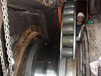
In July 2011, Schaeffler UK received a telephone call from an area works engineer at the BOS Plant, advising of a sudden bearing failure on the non-drive side (NDS) of the V2 BOS plant vessel.
The BOS Plant engineers arranged a meeting and a request was made for two engineers from Schaeffler Germany to be on site at Port Talbot soon afterwards. A meeting subsequently took place at Port Talbot to discuss action plans and how to replace the trunnion bearings.
As Dave Wall, Senior Applications Engineer at Schaeffler UK recalls: “A method statement document was drawn up by Schaeffler UK, which specified the sequence and method to replace the bearings and outline the TATA requirements. Included in this document was a detailed tooling list and a step-by-step procedure for the dismounting and mounting of the drive-side (DS) & non drive-side (NDS) bearings.”
“The standard ‘solid’ bearing on the DS was replaced by a special FAG split spherical roller bearing [SSRB], which is the recommended replacement spare, as this reduces the amount of downtime when installing the replacement bearing. The NDS bearing was to be replaced with a similar solid bearing. In addition, various surrounding components also required replacing, once the secondary damage caused by the bearing failure had been identified,” confirmed Wall.
Removal of the Drive Side bearing
The cutting away of the existing bearing took a total of 36 hours. The distance between the trunnion spacers (bearing seating width) was measured in order to determine the thickness required for two special, TATA designed, split ‘dovetail’ spacers. These were required to ensure that the new split bearing would be correctly secured in place.
The new split SRB inner ring halves with clamping rings, outer ring half and bottom roller cage halves, were fitted without any problems.
Removal of the Non-Drive Side bearing
The original bearing on the NDS had failed during operation, which had caused the BOS converter to drop down. It was now resting on the bearing housing and the housing covers.
After lifting, parts of the damaged bearings were removed, including cage pieces; outer and inner ring fragments and rolling elements. All the components were sent for forensic examination to TATA Central Engineering Metallurgy & Inspection Dept. The housing back cover, bearing pressure plate and sleeve spacer were found to be seriously damaged. New ones had to be urgently manufactured by Tata Steel’s Central Engineering Shops (CES). The bearing inner ring had disintegrated and the sleeve had to be cut off due to its deformed shape. After removing the damaged bearing, it was also discovered that the trunnion back spacer was in need of repair. Again, machining work was urgently carried out by CES.
Due to the subsequent damage to the bearing housing, Schaeffler expertise was required to manually repair this surface to restore it back to an acceptable condition.
During the dismounting process the NDS Ladder Expansion Bearing Rollers had to be replaced. To facilitate the Ladder Roller replacement and installation of a TATA manufactured solid inner bearing housing cover, the bottom half of the housing had to be moved away from the journal using specially manufactured crossbeams.
Mounting of the new Non-Drive Side bearing
The new bearing was first pre-mounted to determine the correct sleeve spacer width. The bottom half of the housing was then moved back into position and the crossbeam construction removed.
Mounting of the new bearing was challenging, as the collapse of the original bearing had caused the vessel to move out of alignment.
The lowering of the converter was also a challenge as the vessel had to be moved sideways by 40mm to achieve the correct installation position. Side shifting was initially a problem for the vessel lifting contractor but the problem was successfully overcome.
Final mounting steps for the NDS and DS bearings
For the DS bearing, the remaining roller cage and outer ring halves were installed. For both bearings, the housing caps were fitted and each bearing was 100 per cent filled with grease, including the surrounding free space.
The housing covers were bolted in position and new seals with their tensioning devices were fitted. After having successfully completed the work in under 2 weeks, Schaeffler engineers were pleased to be leaving behind a very happy customer.
After the bearings were installed, the work didn’t finish there. Schaeffler UK prepared a recommended practical maintenance schedule list and forwarded this to the BOS Engineers, which was well received. In addition, customer “as built” cross-sectional drawings were updated to show the actual parts (with measurements) now in place at V2. Schaeffler UK participated and contributed to the Bearing Failure Review meetings with Tata Steel that followed the bearing replacement for the BOS vessels.
“Since replacing the trunnion bearings, engineers from Schaeffler UK have also supervised two further BOS vessel bearing changes in a very short timeframe of just two months: Converter C at SSI UK / Teesside and Converter 1 at Tata Steel Port Talbot. Schaeffler has now been selected as the preferred supplier of main trunnion bearings for the two BOS plant vessels at Tata Steel Port Talbot,” confirms Dave Wall.
Schaeffler (UK) Ltd,
Forge Lane
Sutton Coldfield
West Midlands B76 1AP
Tel: 0121 313 5870 Fax: 0121 351 7686
e-mail: This email address is being protected from spambots. You need JavaScript enabled to view it.This email address is being protected from spambots. You need JavaScript enabled to view it.
www.schaeffler.co.uk
 Leaking oil tanks repaired in-situ with fast-curing epoxy composite
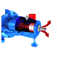 The reliability of most rotating equipment is almost inevitably linked directly to bearing life, and it is estimated bearing failure is responsible for almost 21% of these equipment failures (Bloch, 2011).
 The art of measuring low-frequency vibrations
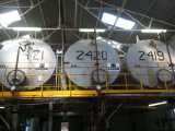
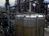 Molten sulfur is present in an ever widening range of industries and liquid sulfur storage tanks are used worldwide in crude oil refineries and natural gas plants to store liquid sulfur in very large volumes. Sulfur storage tanks are most commonly utilised as part of the Gas Treating System in sour crude oil refineries and gas sweetening facilities to temporarily store liquid sulfur produced in the sulfur recovery plant. These tanks are usually field erected and most commonly constructed of carbon steel.
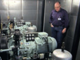 Helium has the lowest boiling point of all gases at -269 °C. As a result, liquid helium is frequently used as a cooling medium. This is the case at the Jülich Research Centre (FZJ). “Nowadays we mainly use liquid helium for cooling superconductors in computer tomographs, for example for brain research and biotechnology”, says Ulrich Sieberichs, supervisor in the supply department for cryogenic gases at the FZJ.
 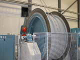 At the Renström mine in northern Sweden, Swedish mining company Boliden monitors the mechanical condition of the multi-rope friction hoist using
  Introduction
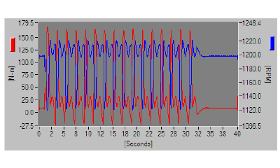
 Lifecycle Cost Analysis: The Key to Asset Sustainability