Boilers & Burners - Statistics
Corrosion Mitigation of an Amine Regeneration Column
Case Study Summary
Inspection identified accelerated corrosion of the pressure vessel shell in an amine regenerator column. IGS mobilised rapidly and performed an on-site alloy upgrade using its proprietary HVTS® technology. This intervention prevented costly structural replacement and avoided an extended unplanned shutdown, delivering estimated savings of approximately $40 million through avoided capital expenditure and minimised production interruption. The cladding remained in place until the end of the vessel’s service life.
This case study represents one of 500+ pressure vessels IGS has protected over the past 25 years.
Introduction
During a scheduled shutdown inspection in April 2010 at an amine facility, severe corrosion was discovered inside an Amine Regeneration Column (Figure 1). The internal surfaces of the lower section of the carbon steel column exhibited extensive wall loss and pitting. The inspection report detailed general corrosion below trays 21–22, with wall thickness measured between 13.1–13.5 mm and localized pitting up to 2.3 mm deep. A circumferential corrosion band approximately 470 mm wide was found around the full circumference. Similar but shallower corrosion was also noted at trays 18–19, with maximum depth of 1.4 mm and wall thickness between 13.2–13.8 mm (Figures 2&3).
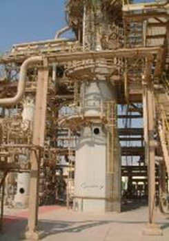
Figure 1. Amine regenerator column
Root Cause Analysis
The root cause of this unexpected corrosion was traced to a tube failure in the associated reboiler. This failure resulted in localised acid attack where the reboiler feed entered the column via an inlet nozzle. The operator’s primary concern was determining whether the column required structural repair or full replacement, both of which would entail significant capital expenditure, extended downtime, and substantial losses. Replacement was dismissed due to long procurement lead times, while internal weld overlay repair would have required post-weld heat treatment (PWHT) and external structural support to prevent collapse during the process, with a lead time of 3-4 months. These complications rendered both options unattractive.
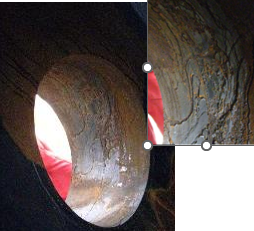
Figure 2&3. Severe corrosion of the internal vessel surface
Engineering Assessment
A third-party engineering company conducted a comprehensive Fitness-For-Service (FFS) assessment in accordance with API 579 / ASME FFS-1 (2007) (Figure 4). Stress and buckling analyses under operating and design conditions confirmed that the vessel remained structurally sound, even in its corroded state. The minimum allowable shell thickness was calculated at 7.9 mm, with a localized minimum of 6.6 mm under the inlet nozzle. This verification allowed continued operation under close monitoring while corrosion mitigation measures were implemented.
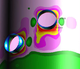
Figure 4. FFS Assessment – combined primary stresses
IGS HVTS Solution
To stop further metal loss and protect the column’s pressure boundary, Integrated Global Services (IGS) was engaged to apply its proprietary HVTS® (High Velocity Thermal Spray) internal cladding system. The solution forms a dense, corrosion-resistant barrier without generating heat-affected zones (HAZ) or requiring PWHT, allowing in-situ restoration and protection of critical process equipment with minimal downtime.
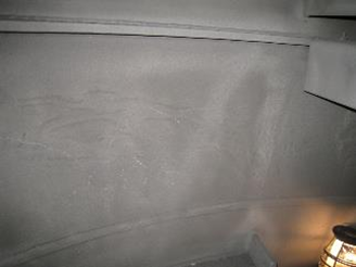
Figure 5. Finished HVTS application
Having personnel and equipment already mobilized in-country, IGS was able to respond immediately. Following inspection of the corroded areas, the internal surfaces were prepared and treated using the HVTS process to establish a durable, corrosion-resistant barrier. The cladding was applied to specification and verified to ensure full protection of the column’s pressure boundary.
Results and Performance
The HVTS cladding was completed, inspected, and the trays reinstalled before the column was sealed in mid-May 2010. Subsequent inspections confirmed the cladding’s integrity and the absence of further metal loss. After two years of stable operation and no detectable reduction in wall thickness, the operator cancelled the replacement order for the new column.
The column remained in service until the end of 2015, when it was decommissioned as part of a process upgrade to increase production capacity (Figure 6). The use of HVTS in 2010 prevented costly structural replacement and avoided an extended unplanned shutdown, yielding estimated savings of approximately $40 million through avoided capital costs and minimized production interruption.
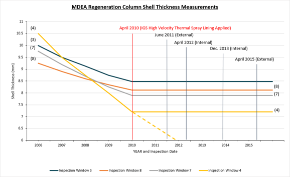
Figure 6. MDEA Regeneration column shell thickness measurements
To find out more about HVTS, visit www.integratedglobal.com

Explore EMS
More Editorial
Directory
This website is owned and operated by: MSL Media Limited
Co. Number: 05359182
© 2005 MSL Media Ltd. All rights reserved. E&OE