
By Steven Zhang, Product Manager, Powernexu Technology Co Limited
Power-supply failures in industrial control systems are often treated as sudden events. In practice, many failures develop gradually through rising temperature, ageing components, restricted airflow, increasing load or deteriorating connections.
For maintenance teams, the challenge is identifying these warning signs early enough to act before a power problem stops a PLC, industrial PC, I/O system or communications network.
The power supply should therefore be treated as a maintainable asset rather than a component that is replaced only after failure.
Temperature Is Often the First Warning Sign
Heat accelerates stress on many PSU components, including electrolytic capacitors, semiconductors, connectors and cooling fans.
A rising PSU temperature does not automatically mean failure is imminent, but a change from the unit’s normal thermal pattern can be useful maintenance information.
Engineers should monitor the actual air temperature entering the PSU rather than relying only on the temperature of the room or control cabinet.
Blocked filters, dust accumulation, failed fans and cable congestion can all reduce effective airflow.
Thermal imaging can also help identify unusually hot connectors, terminals or sections of the power supply.
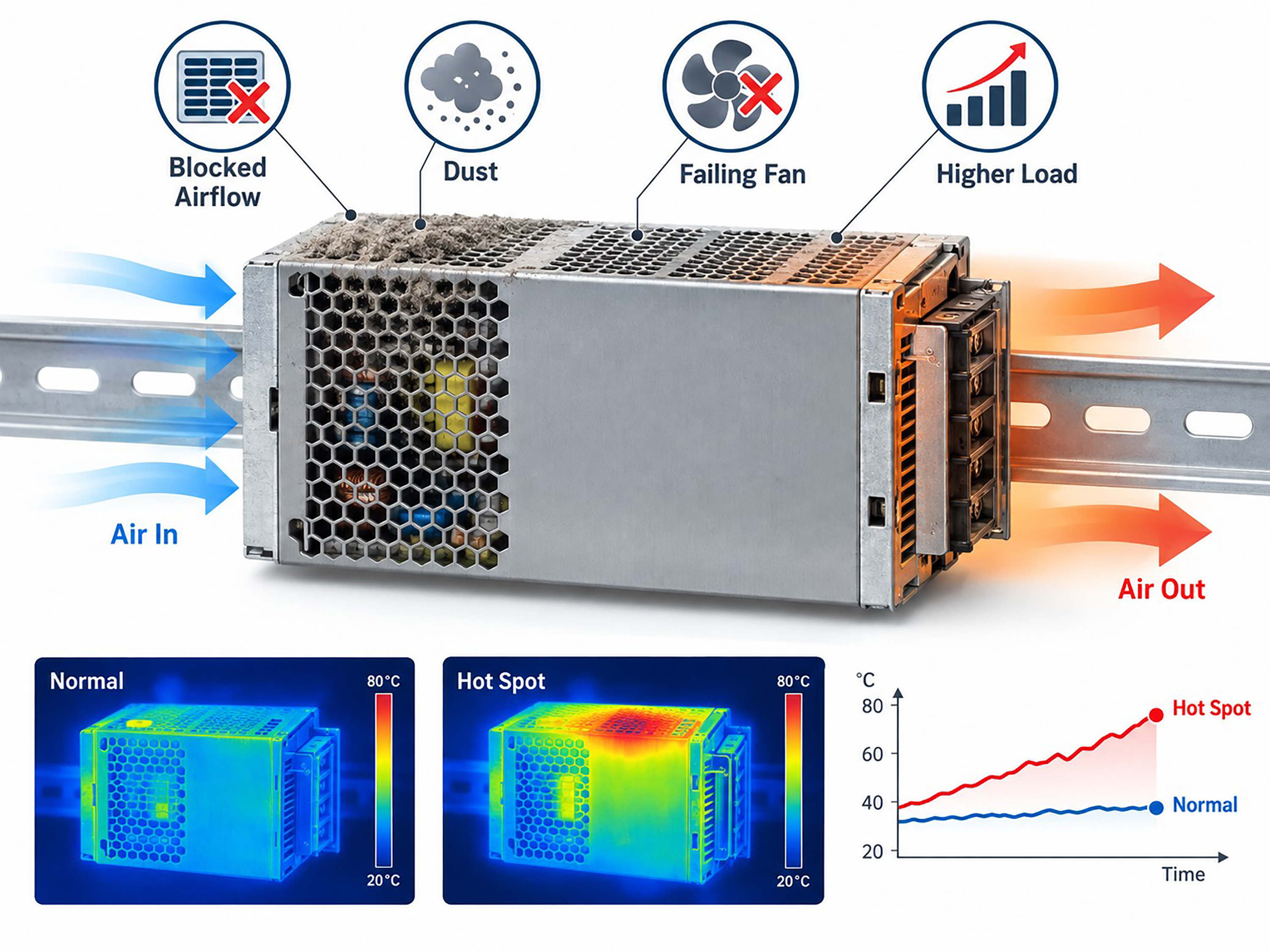
Figure 1 – Industrial PSU Thermal Warning Signs
A useful maintenance practice is to compare temperatures under similar machine loads. A PSU that operates noticeably hotter than it did several months earlier may deserve further inspection even if its output voltage is still within specification.
Load Growth Can Reduce Reliability Margin
Industrial systems rarely remain unchanged throughout their lifetime.
Additional sensors, I/O modules, communication devices, industrial PCs or auxiliary equipment may be added without reviewing the original power budget.
The PSU can therefore move gradually from moderate utilisation toward continuous high load.
This reduces the available margin for:
- Startup current
- Temporary overloads
- Higher ambient temperature
- Component ageing
- Future expansion
Maintenance teams should periodically compare actual current or power consumption with the PSU’s rated capability and the manufacturer’s derating limits.
A supply that was comfortably sized when the machine was commissioned may no longer have the same margin several years later.
Voltage and Fault Trends Can Reveal Developing Problems
A single output-voltage measurement provides only a snapshot.
Trend information is much more useful.
Where monitoring is available, engineers should watch for changes in:
- Output voltage
- Output current
- PSU temperature
- Fan speed
- Input voltage
- Warning or fault status
- Redundancy status
Repeated undervoltage warnings, temperature alarms or brief protection events should not simply be cleared and forgotten.
They can indicate increasing load, poor cooling, unstable input power or a developing PSU problem.
Modern digitally managed supplies may provide telemetry through interfaces such as PMBus, while simpler industrial PSUs may provide DC_OK, alarm contacts or status signals.
Even basic signals become valuable when maintenance teams record and trend them over time.
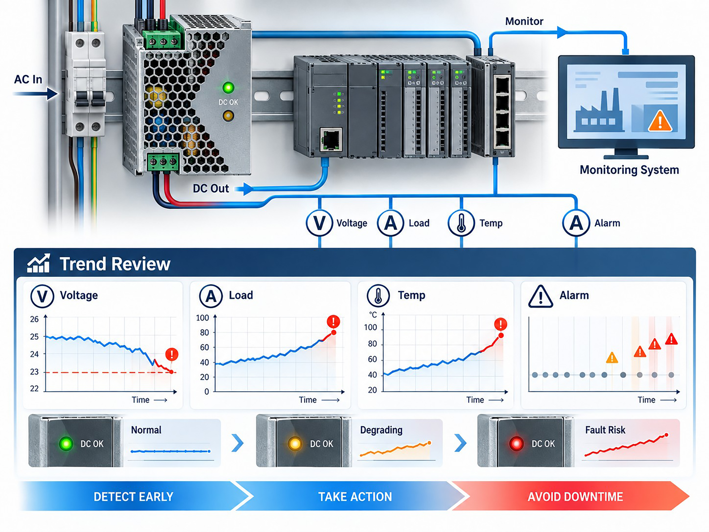
Figure 2 – Industrial Power Monitoring Dashboard
Connections Deserve Attention Too
Not every “power-supply failure” originates inside the PSU.
Loose terminals, oxidised contacts, damaged connectors and poorly terminated cables can increase resistance and create local heating.
At higher current, a small resistance increase can produce significant temperature rise.
Inspection should therefore include the complete power path:
AC input → PSU → distribution terminals → DC cabling → control equipment
Discolouration, damaged insulation, unusual connector temperature or repeated voltage drop under load can all indicate a connection problem.
Redundancy Creates a Maintenance Opportunity
Redundant power architectures can reduce downtime, but only if both power paths are healthy.
A common risk is that one redundant PSU fails silently or remains in a warning state while the system continues operating normally on the remaining unit.
The apparent redundancy has then disappeared.
Maintenance teams should periodically confirm:
- Both modules are online
- Current sharing is reasonable
- No persistent fault is present
- Both input feeds are available
- Hot-swap replacement works as intended
When redundancy is healthy, a deteriorating PSU can often be replaced during planned maintenance without shutting down the control system.
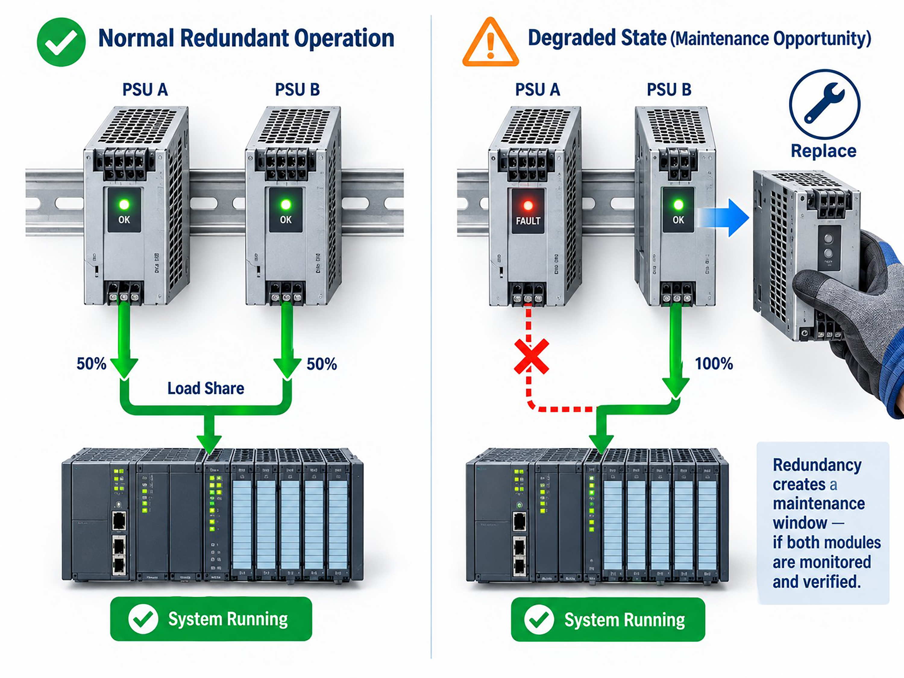
Figure 3 – Redundant Power Supply Maintenance Workflow
Move From Reactive Replacement to Condition-Based Maintenance
The goal is not to replace power supplies unnecessarily.
It is to combine simple indicators—temperature, load, voltage, alarms, airflow and connector condition—to identify units whose operating behaviour is changing.
A practical maintenance routine can include:
- Periodic thermal inspection
- Cleaning filters and airflow paths
- Recording PSU load
- Reviewing alarms and telemetry
- Checking redundant modules
- Inspecting high-current connections
- Planning replacement when multiple warning indicators appear
Power supplies are critical to every electronic control system, yet they are often ignored until a failure occurs.
By monitoring how a PSU behaves over time, maintenance teams can turn many power failures from unexpected production events into planned service activities.
Author Bio
Steven Zhang is Product Manager at Powernexu Technology Co Limited, focusing on server and industrial power supplies, redundant power architectures and power-system integration. His work covers power-delivery reliability, thermal performance and high-density computing and industrial control applications.
Company: Powernexu Technology Co Limited
Website: www.powernexu.com
Email: This email address is being protected from spambots. You need JavaScript enabled to view it.