
CFB Boilers by design offer several advantages over conventional boiler designs, including the ability to fire a wide range of fuels and lower combustion temperatures which reduces emissions. However, one of the common problems with CFB boilers is the exposed tubes in the top two-thirds of the boiler which maximise radiant and convective heat transfer but are vulnerable to erosion.
In this article, we will discuss the damage mechanisms associated with CFB boilers, the solutions available to prevent boiler tube wastage, and look at a case study which highlights these topics in a real-world scenario.
CFB Boiler Damage Mechanisms
Erosion can be found in most CFB boilers, sootblower lanes (dual mechanism of corrosion-erosion), and backpass areas that experience fly ash erosion. The type of corrosion found will depend on the type of fuel, boiler configuration, and combustion atmosphere. The typical corrosion mechanisms include fireside corrosion and reduced atmosphere high-temperature sulfidation and circumferential cracking (also known as stress corrosion cracking, corrosion-assisted thermal fatigue, quench cracking).
Erosion
Fly ash erosion is the second most common cause for boiler tube failure (DOE, 1998). Tube erosion in a CFB combustor can never be stopped, but there are solutions available to slow the wastage down, which will be discussed further on in this article.
Corrosion Content
The material used in CFBs should also be corrosion resistant, with increased chromium (30%+) content, specifically designed for high-temperature erosion/corrosion environments where sulfur and/or chlorides may be present.
Corrosion due to the presence of sulfur
The presence of sulfur in the fuel paired with the presence of oxygen in the atmosphere aids in the formation of FeO and FeS. Sulfide formation may take place underneath scale and deposits on tubes. Over prolonged service time, iron sulfidegets oxidized, producing sulfur. The incipient sulfur is free to attack metal, resulting in a localized corrosion of substrate and material loss.
Corrosion products on the surface of the tube consist of iron oxide and iron sulfide. The FeO and FeS formation reaction is as follows:
Corrosion due to chlorides (in cases of burning waste, or waste combination with coal).
The presence of chlorine in the fuel, especially RPF, exacerbates the corrosion of the waterwall substrate. Though corrosion is not the rate-controlling material loss mechanism, the formation of oxide scales lowers the erosion resistance of the waterwalls. However, chlorine-induced attack is a possibility in boilers that burn plastic fuel. In normal combustion with the presence of the correct amount of oxygen (before low-NOx burners), the sulfur present in the fuel will combine with oxygen and remain in gaseous condition and exit the stack. In combustion under reducing conditions (low oxygen), the sulfur will combine with hydrogen and deposit on the tube surface reacting with the iron of the tube material to form a scale of FeS, and repeat the cycle as more H2S deposits on the walls, causing significant tube thinning.
Inspecting CFB Boilers for Damage
Traditionally, CFB boiler inspections are conducted by assembling scaffolding once the boiler has cooled down and performing a visual inspection inside the boiler. However, in recent times, drone inspection services have become increasingly popular, enabling engineering and maintenance teams to identify and fix damage much earlier during a turnaround.
One of these services is Integrated Global Services’ (IGS) SMARTGard® CFB Boiler Inspection Drone Service which uses advanced drone technology alongside expert boiler inspection knowledge. Performed during the cooling down phase, the service offers a comprehensive view of the condition of a boiler to enhance efficiency, reduce costs, and detect issues earlier.
A team comprising a certified pilot and a CFB inspection specialist collaborate to operate the drone. Together, they manoeuvre the drone to critical areas of the boiler, offering a detailed examination. Each notable point of interest is documented with precise location coordinates, along with high-definition images and video footage.
All inspection data and reports are stored in a protected cloud-based portal. This approach enables easy access, allowing users to review and analyze information at their convenience. Such accessibility facilitates well-informed decisions regarding maintenance, repairs, and overall boiler management.
The SMARTGard® Inspection service provides several advantages, including improved CFB boiler availability. By promptly identifying potential issues and continuously monitoring the boiler's condition, proactive measures can be implemented, minimizing downtime, and maximizing productivity. Additionally, the service significantly reduces costs associated with extensive scaffolding, making SMARTGard® a cost-effective solution for boiler inspections.
Al Geraskin, who developed the SMARTGard® drone program, said: "There are several drone inspection services available on the market, however IGS is currently the only company that has combined its 40-year expertise in boiler reliability with drone technology to not simply fly the drone around the boiler but to focus on critical areas and advise on the best course of action.”
The Solution: Integrated Global Services (IGS) High Velocity Thermal Spray (HVTS)
Extending the life of the tube is possible with the use of added material to the OD surface of the tube, with Inconel Weld Overlay or High Velocity Thermal Spray (HVTS) Cladding. The purpose of adding material to the tube is to extend its useful life, ultimately preventing panel replacement.
HVTS Material Science
IGS material is a High Velocity thermal sprayed metal cladding suited for a broad spectrum of both low and high temperature erosion/corrosion environments. The alloy has been specifically designed for use in high erosive and abrasive boiler environment. NiCr binder composition, with high Cr content makes it particularly resistant to high temperature sulfidation conditions. The alloy also has good high temperature oxidation resistance. A thermal expansion coefficient at the midpoint between carbon and stainless steels makes it well suited to both as substrate materials. The material has good erosion resistance due to effective Boron and Carbon induced hard-phase integration in a ductile binder.
The IGS cladding has excellent erosion resistance. Although it is a hard cladding system, it has greater ductility and can be repaired and rebuilt easily. It is widely used for erosion/corrosion protection in the CFBs. The erosion/corrosion protection of the waterwalls with IGS cladding system will increase the service life of the boiler, eliminate unplanned downtime, and increase the efficiency of the plant.
Minimum bond strength: > 5000 psi (ASTM D4541)
Microhardness: > 900HV300g (66.5 HRC)
The benefits of HVTS cladding include:
SMARTGard: A Smarter Way to Guarantee CFB Boiler Reliability
SMARTGard is a turnkey service offered by IGS in which its proprietary High Velocity Thermal Spray (HVTS) alloy clad solution is applied. However, the service goes beyond simply applying the cladding. It is a comprehensive maintenance service that starts with a detailed analysis of the boiler including previous maintenance and reliability history. After a full inspection, HVTS is applied which provides long-term protection from high-temperature corrosion and erosion of CFB boiler tubes. Finally, results are measured, documented, and monitored alongside a proactive maintenance schedule. SMARTGard is a complete service that guarantees boiler reliability.
Case Study: Proactive CFB Boiler Maintenance Saves $ Millions and Triples Run Cycles
Introduction
This coal-burning boiler was commissioned in 1998 with an 11,450 sqft (1064 sq.m.) heating surface and 1.2 million pounds per hour (544 t/h) steaming cap. IGS first applied HVTS in 2020 and monitored the condition of the boiler over two years.
The Problem
The annual cost from forced outages, RIK, general maintenance, and electrical cost associated with each unit could reach an average of 8-12 Million dollars.
The Solution
IGS HVTS addressed the problems and increased the run cycles from 4-6 months to 12-14 months with no forced outages and minimal time needed for welding and cladding repair
.
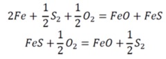
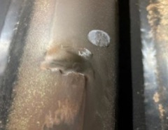
See the bare tube condition prior to the IGS HVTS application. Notice hard edges around discontinuity from erosion damage where ash build-up has deviated material flow into the unprotected substrate.
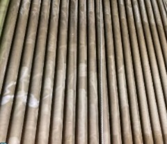
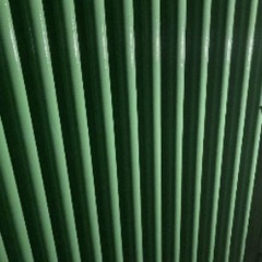
3. Ceramic Top Coat
Once the cladding process has been completed, IGS applies a proprietary ceramic top coat as a wear indicator during future outage inspections to help navigate future coating plans.
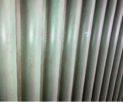
The coated area after a 14-month run cycle appears on the right. The presence of ceramic top coat (Green) can still be identified meaning underlying thermal spray cladding is still at 100% as-applied condition.
The Benefits of HVTS
HVTS cladding reduces tube wear and increases overall production. This reduces costs associated with maintenance from both planned maintenance and forced outages. Reducing the need for welding and eliminating the requirement for refractory in some areas minimizes critical path time needed for other trades and increases available heated surface.
To find out more about protecting CFB Boilers, contact IGS for a response within 24 hours.
This article can alos be found in the issue below.
